


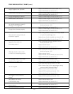

External Battery Pack:
Sealed package containing rechargable cells, fuse and wiring harness.
1.2 DETAILED DESCRIPTION
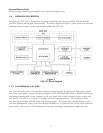
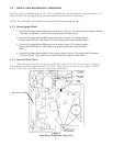
Internally, the GPS 155 is divided into six printed circuit boards: the main, RF/IF, altitude decoder,
interface, display, and keypad circuit boards. The block diagram in Figure 1 below shows the interrela-
tionships between major circuits and modules within the GPS 155.
Figure 1
GPS 155 Block Diagram
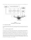
1.2.1 Control/Display Unit (CDU)
The Control/Display Unit is an assembly consisting of ten keycaps, keypad board, light pipes optical
lens, front insert panel, vacuum fluorescent display (VFD) and board with drivers, display board shock
mounting grommets and screws, housed in a die cast bezel with a dual concentric rotary switch and
two knobs. The VFD is a 3 row by 20 column unit with variable intensity. This display provides
excellent day and night visibility from wide viewing angles. The front panel provides function selec-
tion and alphanumeric input to the Main Board Assembly via 10 push-buttons and the dual concentric
rotary knob. There are two LEDs behind each keycap, providing backlighting for night time use.
2