


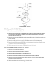


Figure 7
RF/IF Assembly Removal
3.2.6 Battery Pack (011-00067-00) Removal
1. Remove the covers as described in Section 3.1.
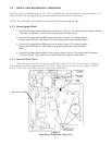
2. Remove the heat sink clamping bar (115-00049-00, see Figure 12-Detail A) by removing the M3 x 5mm mounting
screw (211-50227-05). (Note: Removal of the Altitude Decoder, Interface and Main Boards is not required to
remove the battery pack from the unit.)
3. Remove the heat sink insulator (250-00016-00) from the regulator I800 (see figure 12-Detail A) and save this piece
for later reassembly.
4. Remove the two M3 x 5mm flat head screws (211-00024-00) which attach the CDU to the battery pack.
5. Remove the three M3 x 5mm screws (211-50227-05) securing the battery pack to the chassis. (Note: One screw
is recessed in a hole on the side of the battery pack.)
6. Slide the battery pack cable and connector (P800) through the cutout in the chassis.
3.2.7 Power/Dimmer Switch (011-CS032-00) Removal
1. Remove the covers as described in Section 3.1.
2. Remove the Control/Display Unit as described in Section 3.2.1.
3. Remove the Main Board Sub-Assembly as described in Section 3.2.4.
4. Remove the coupling sleeve (125-00021-00) by unscrewing the pivot pin screw (211-00030-00).
5. Remove the hex nut securing the power/dimmer switch to the chassis. This nut is 7/16” and may be removed
with a deep, thin-walled 12-point socket.
6. Slide the power/dimmer switch out of the mounting hole on the chassis.
14
012-00091-00
012-00091-00