


Bettis P/N 124840E
Revision “B”
Page 36 of 46
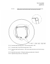
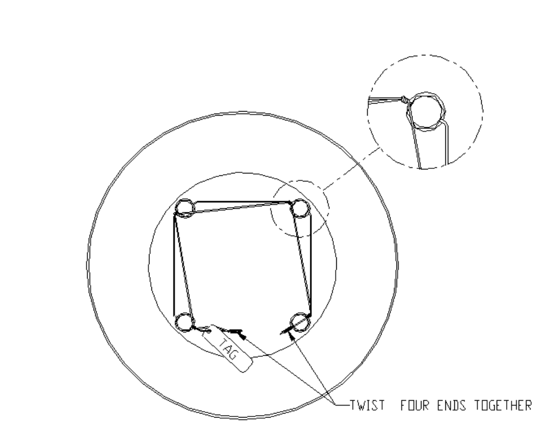
5.2.15.5 Attach caution tag and twist tie the wires from the last screw head to the
twisted wires of the first screw head. See following for illustration.
5.2.16 If removed install stop screw nuts (1-190) onto stop screws (1-180).
5.2.17 If removed install o-ring (2-90) onto stop screws (1-180).
5.2.18 If removed install two stop screws (1-180) into two stop screw holes on the front of housing
(1-10).
5.2.19 Adjust both stop screws (1-180) back to settings recorded earlier in Section 5.
5.2.20 Tighten both stop screw nuts (1-190) securely.