


Bettis P/N 124840E
Revision “B”
Page 35 of 46
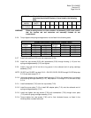
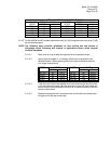
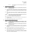
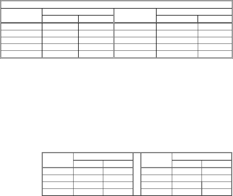
HEX CAP SCREWS (7-20) TORQUE TABLE
TORQUE ±5 % Percent TORQUE ±5 % PercentHOUSING
MODEL
(FT-lb.) N-m
HOUSING
MODEL
(FT-lb.) N-m
G01 30 41 G7 135 183
G2 30 41 G8 240 325
G3 30 41 G10 285 386
G4 65 88 G13 340 461
G5 65 88
5.2.15 On M3, M3HW and ES models install Monel wire (6-130) through each hex cap screw (7-20)
per the following steps:
NOTE: The following steps provides guidelines for wire locking hex cap screws to
discourage screw loosening and removal in applications where screw removal
could be hazardous.
5.2.15.1 Make sure hex cap screws are tightened to their specified torque.
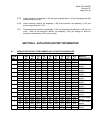
5.2.15.2 Using required lengths of .31 diameter Monel wire as provided in the
Module ordered. When replacing Monel wire use the following table for
wire length requirements.
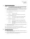
LENGTH LENGTHMODEL
Inch mm
MODEL
Inch Mm
G01-SR 36 914.4 G5-SR 66 1676.4
G2-SR 44 1117.6 G7-SR 79 2006.6
G3-SR 48 1219.2 G8-SR 88 2235.2
G4-SR 55 1397.0 G10-SR 110 2794.0
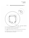
5.2.15.3 Twist the end of both wires together and insert one through the drilled hole
in the hex cap screw head, pass the second wire over the screw head and
twist it three (3) times around the first wire at a location where the first wire
exits the screw head.
5.2.15.4 Repeat the procedure until the second wire is twist tied to the screw head
through wire of the last screw head.