


Bettis P/N 124840E
Revision “B”
Page 18 of 46
3.2.48 Adjust both stop screws (1-180) back to settings recorded earlier in Section 2 at step 2.3.2.
3.2.49 Tighten both stop screw nuts (1-190) securely.
3.3 PNEUMATIC POWER MODULE REASSEMBLY
NOTES: 1. For early model G2 and G3 actuators with double nuts on the power
module use section 3.4 for reassembly.
2. Refer to Section 2 step 2.1.4 for the correct installation location for piston
rod (3-40).
3. THE ACTUATOR MUST BE IN THE APPROPRIATE OVERTRAVEL
POSITION. Confirm over-travel position by observing the guide block
(1-30) is against the inner wall of housing (1-10).
3.3.1 Lubricate piston rod (3-40) and insert through the side of housing (1-10).
3.3.1.1 G2 through G13 screw piston rod (3-40) onto extension rod assembly (1-50).
3.3.1.2 G01 only screw piston rod (3-40) onto guide block (1-30).
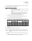
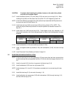
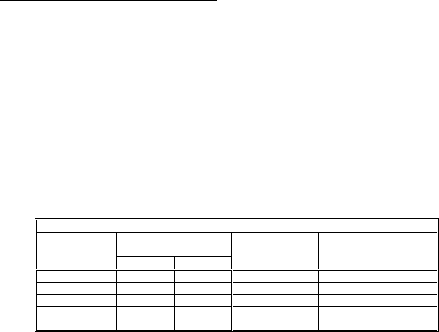
3.3.2 Torque tighten piston rod (3-40) to the lubricated torque as listed in the following table.
PISTON ROD TORQUE INFORMATION
TORQUE
(±5 % Percent)
TORQUE
(±5 % Percent)
HOUSING
MODEL
FT-lb. N-m
HOUSING
MODEL
FT-LB N-m
G01 90 122 G7 240 325
G2 90 122 G8 240 325
G3 90 122 G10 240 325
G4 240 325 G13 240 325
G5 240 325
3.3.3 Refer to assembly drawing page 2 of 2 Detail "C". Install one rod wiper (4-10) into inner
end cap (3-10).
3.3.4 Install one rod bushing (4-20) into inner end cap (3-10).
3.3.5 Coat one Polypak seal (4-30) with lubricant and install, lip first, into inner end cap (3-10).
CAUTION: Install the Polypak seal with energizer ring facing outboard side (away from
housing).
3.3.6 Install one o-ring seal (4-90) into seal groove located on the inboard face of inner end cap
(3-10).
3.3.7 Install inner end cap (3-10) on to housing (1-10). NOTE: The pressure inlet port should be
positioned in the same position as recorded in section 2.2 step 2.2.1.