


Bettis P/N 124840E
Revision “B”
Page 34 of 46
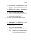
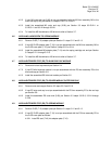
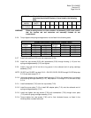
WARNING: After initial thread engagement the tension rod must be rotated
clockwise the minimum number of turns listed in the following
table.
ACTUATOR
MODEL
TORQUE
UNITS
G01 G2 G3 G4 G5 G7 G8 G10 G13
MINIMUM
NO TURNS
N/A 6 10 10 10 13 14 20 25 31
WARNING: When screwing tension rod into extension rod assembly (9-50) make certain
that the tension rod and extension rod assembly threads do not
cross-thread.
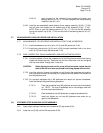
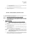
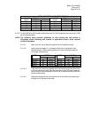
5.2.6 Torque tighten the spring cartridge tension rod as listed in the following table.
SPRING CARTRIDGE TENSION ROD TORQUE TABLE
HOUSING TORQUE (±5 % Percent) HOUSING TORQUE (±5 % Percent)
MODEL FT-Lb. N-m MODEL FT-Lb. N-m
G01 50 68 G7 240 325
G2 90 122 G8 240 325
G3 90 122 G10 240 325
G4 240 325 G13 240 325
G5 240 325
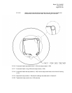
5.2.7 Install lock washers (5-30) onto hex cap screws (5-20).
5.2.8 Install hex cap screws (5-20) with lockwashers (5-30) through housing (1-10) and into
spring cartridge assembly (5-10) and tighten.
5.2.9 Install o-ring seal (6-10) into the o-ring groove in the outboard end of spring cartridge
assembly (5-10).
NOTE: G2-SRF and G3-SRF use step 5.2.10. G01-SR, G2-SR, G3-SR through G13-SR skip step
5.2.10 and start at step 5.2.11.
5.2.10 Using pipe sealant on the threads install pipe plug (7-10) in the vacant hole in out board
end of spring cartridge assembly (5-10). Skip steps 5.2.10 through 5.2.13 and start at step
5.2.14.
5.2.11 Install lockwashers (7-30) onto hex cap screws (7-20).
5.2.12 Install the cover plate (7-10) or install M3 adapter plate (7-10) onto the outboard end of
spring cartridge assembly (5-10).
5.2.13 Install and tighten hex cap screws (7-20) with lockwashers (7-30) through cover plate
(7-10) and into spring cartridge assembly (5-10).
5.2.14 Torque tighten hex cap screws (7-20) until a final lubricated torque, as listed in the
following table, has been achieved.