


Bettis P/N 124840E
Revision “B”
Page 24 of 46
CAUTION: If needed, when installing the cylinder, hammer on the end of the cylinder
only with a non metallic object.
3.4.17 Install lubricated cylinder (3-70) over piston (3-30) and onto inner end cap (3-10). When
installing the cylinder over the piston seal tilt cylinder 15° to 30° degrees to piston rod.
NOTE: If the Power Module is equipped with a M3 jackscrew pre-assemble the M3 jackscrew to
the outer end cap (3-80) per Section 3.6.
3.4.18 Install outer end cap (3-80) over tie bars (3-20) and into cylinder (3-70). NOTE: The
pressure inlet port should be positioned in the same position as recorded in section 2.2
step 2.2.1.
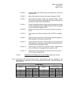
3.4.19 Install tie bar nuts (3-90) onto tie bars (3-20). Torque tighten tie bar nuts, alternately in 100
foot pound increments, until a final lubricated torque, as listed in the following table, has been
achieved.
TIE BAR NUTS
TORQUE
(±5 % Percent)
TORQUE
(±5 % Percent)
HOUSING
MODEL
FT-lb. N-m
HOUSING
MODEL
FT-lb. N-m
G2 120 163 G3 150 203
3.3.20 Install lockwashers (3-140) onto socket cap screws (3-130) ).
3.4.21 Install and tighten socket cap screws (3-130), with lockwashers (3-140), into outer end cap
(3-80).
3.4.22 Install Pneumatic Power Module per Section 5 steps 5.4.
3.5 BLIND END CAP MODULE INSTALLATION
NOTE: If the blind end cap has an M3 jackscrew or ES stop screw that has been removed from
the blind end cap then pre-assemble the M3 or ES into the blind end cap per Section 3.6 or
3.8.
3.5.1 Install o-ring seal (6-10) into the o-ring groove in blind end cap (5-10).
3.5.2 Install lockwashers (5-30) onto hex cap screws (5-20).
NOTE: Verify that steps 3.2.14 and 3.2.15 have been completed prior to commencing with step
3.5.3.
3.5.3 Install blind end cap (5-10) onto end of housing (1-10).
3.5.4 Install and tighten hex cap screws (5-20) with lockwashers (5-30) through housing (1-10)
and into blind end cap (5-10).