


Instruction Manual MM850481 ed.01
6 CONNECTIONS
6.1 Electro-pneumatic connections
To prepare the instrument for operation connect the sampling probe to the instrument:
• Plug the pneumatic connector of the probe to the GAS INLET connector. If you are using the gas sampling probe
with Draft option, connect also its connector to the instrument Pressure/Draft inlet.
• Plug the probe temperature sensor plug to the pertinent connector.
• For more accurate readings and efficiency calculations, plug the remote air temperature Pt100 sensor to the 3 pin
connector on the left side of the instrument.
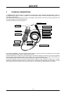
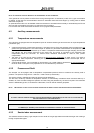
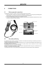
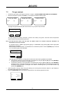
pneumatic ports
Right side
P1 – Draft/Pressure
inpu
t
INLET – gas input
P2 – differential
pressure input
Tgas inpu
t
IR serial interface
RS232 – External
probes input
Battery charger
Pt100 Tair input
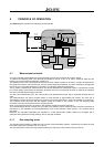
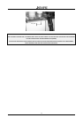
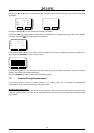
6.2 Gas probe positioning
The measurement site should be arranged at a distance of 2xD behind the exhaust gas connection pipe, where D =
diameter of the exhaust gas connection pipe.
To position the sampling probe in the exhaust gas pathway a hole of 11/16mm should be drilled and the retaining cone of
the sampling probe firmly screwed in it.
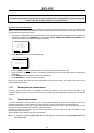
The retaining screw in the cone enables the probe to be easily moved in order to locate the core flow, normally
correspondent to the center of the section of the stack.
The flue gas and exhaust gas pathways, must be checked for gas-tightness before carrying out a measurement and, if
necessary, non gas-tight points should be sealed.
To locate the gas core flow, insert progressively the sampling probe and read the maximum value of temperature.
16