


Instruction Manual MM850481 ed.01
4 PRINCIPLE OF OPERATION
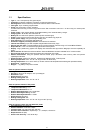
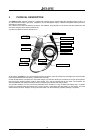
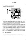
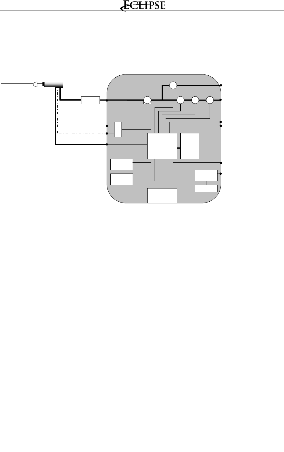
The EGA4 analyzer is based on the following functional blocks:
MicroController
Impact printer
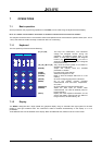
Keyboard
Display
250
memory
Power supply
Ni-MH battery
Battery charger input
External probe input
Pt100 Tair input
Gas outlet
P2 -
∆
P
P1 – Draft/Pressure
Differential
pressure
sensor
Gas input
INLET
Pump 1° Sensoe O2
3° Sensor
TcK Tgas inpu
t
Water trap
Line filter
IR serial port
2° Sensor CO
4° Sensor
4.1 Measurement principle
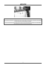
The gas is sampled and aspirated through the probe with a primary pump powered at constant voltage.
To position the sampling probe in the exhaust gas pathway a hole of 11mm, up to 16mm, should be drilled and the
retaining cone of the sampling probe firmly screwed in it.
The retaining screw in the cone enables the probe to be easily moved to locate the core flow, normally correspondent to
the center of the section of the smoke tube. The flue gas and exhaust gas pathway, should be checked for gas-tightness
before carrying out a measurement and, if necessary, non gas-tight points should be sealed.
The O
2
sensor is essentially an electrochemical cell, with two electrodes and electrolyte solution. The behavior is similar
to a normal battery and therefore the sensitivity decreases with time. The expected life does not relate to the operative
time and is lost after approximately 24 months.
The toxic gas measurements (CO, SO
2
, NO and NO
2
) use electrochemical cells, with an expected operative life of 3
years.
The electrochemical cell grants accurate results for time intervals of approximately 60 minutes. The zero drift is
automatically corrected by the instrument every time the instrument is switched-on, using fresh ambient air as reference.
This operation should be made with the sampling probe not inserted in the chimney or with the sampling probe
pneumatic connector disconnected from the analyzer gas inlet.
When a long time analysis has to be made, a new autozero procedure should be performed.
The pressure/draught sensor is based on the principle of the extension metric measuring bridge. When the instrument is
switched-on, a zero calibration of the draught/pressure circuit is also executed. Leave open the “∆P” connector during
this phase.
Measured and calculated parameters are indicated on a LCD alphanumeric display (40x56 mm), equipped with a
automatic back light device for easy readings, also in poor light conditions.
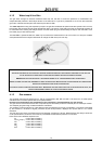
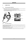
4.1.1 Gas sampling probe
The sampling probe consists of a steel tube and a handle of thermoinsulating material. A positioning cone allows to place
the probe in holes with a diameter from 11 to 16 mm.
The gas temperature is acquired using a thermocouple type K with the junction placed on the top of the tip.
11