


Instruction Manual MM850481 ed.01
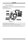
3 PHYSICAL DESCRIPTION
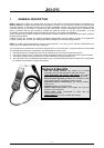
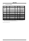
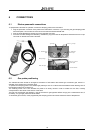
The EGA4 portable analyzer consists of a rugged and compact case, a mother board with all base function circuits, 2, 3
or 4 electrochemical cells, a gas pump, a keyboard, an LCD backlighted display, a Ni-MH rechargeable battery pack and,
optionally an impact printer.
The 2 pieces of the case are jointed by 8 screws. The batteries, the pneumatic circuit and the cells are positioned in the
rear of the analyzer and 2 screws locked the lid.
A pressure lid allows to remove the paper roll.
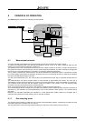
Positionin
g
cone
Flue gas probe
Water trap + Line filter
Impact printe
r
(
o
p
t.
)
Gra
p
hic Dis
p
la
y
Keyboard
Tgas Inpu
t
P2 -
∆
P Inpu
t
P1 – Draft/Pressure
in
p
u
t
INLET – Flue Gas
inpu
t
IR serial
p
ort
Battery charger
External probe input
Back-light sensor
Pt100 Tair probe
At the bottom of EGA4 you can see all sampling probe connectors: gas inlet, pressure and draught input, thermocouple
input for gas measurement and the 2
nd
pressure inlet connector.
On the left side are the connectors for: line power charger, synchronous serial input connector for bar pen and keyboard,
the input for the auxiliary probes (T+RH%, leak checker, etc.) and the infrared LED for PC serial communication (an
optional IR/RS232 and software should be used to configuring and transfer the analysis data).
The operator interface is on the front of the instrument and it consists of: a high contrast LCD display and a 14 button
keypad. An automatic back-light device and a “zoom” function, make easier the data reading on the display. The most
used operation (analysis, draught, printing and smoke index) can be accessed by operator pressing a single key.
10