SKU 91315 For technical questions, please call 1-800-444-3353. Page 9
To Attach The Hydraulic Pump To The Scissor Lift:
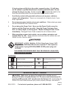
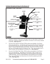
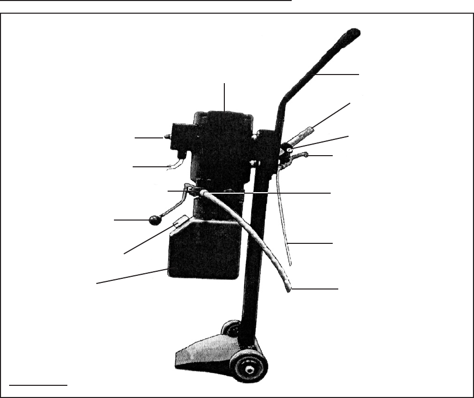
HYDRAULIC PUMP - SIDE VIEW
MOTOR
(1A)
POWER
SWITCH
POWER CORD
OIL PIPE CONNECTOR
(17B)
BRAKE STEEL CABLE
(10B)
BRAKE LEVER ASS’Y.
(13B)
HANDLE
(11B)
PRESSURE RELIEF
VALVE HANDLE
(3A)
OIL TANK
(13A)
OIL TANK FILL CAP
DOLLY ARM
FIGURE D
GENERAL INLET PIPE
(18B)
HYDRAULIC OIL DELIVERY PORT
BOLT (14B)
Locate the Hydraulic Pump unit (1A through 15A) in an area where it will be out
of the way, is safe from damage and weather, and where it can be easily reached
to operate. (See Figure D.)
One end of the General Inlet Pipe (18B) has been pre-attached to the Scissor
Lift by the manufacturer. To attach the remaining end of the General Inlet Pipe to
the Hydraulic Pump wrap the male threads of the Oil Pipe Connector (17B) with
about 4” of pipe thread seal tape (not included). Remove the Oil Filler Nut Cap
(4A) from the threaded Hydraulic Oil Delivery Port. Then, wrench tighten the Oil
Pipe Connector into the Hydraulic Oil Delivery Port. (See Figure D.)
One end of the Brake Steel Cable (10B) has been pre-attached to the Scissor
Lift by the manufacturer. The Brake Lever Assembly (13B) is located on the
remaining end of the Brake Steel Cable, and must be attached to the Handle
(11B) of the Dolly. To do so, slide the Brake Lever Assembly onto the Handle.
Then, secure the Brake Lever Assembly to the Handle by tightening the Bolt
(14B). (See Figure D.)
1.
2.
3.


