SKU 91315 For technical questions, please call 1-800-444-3353. Page 15
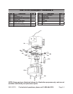
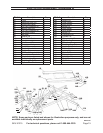
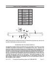
NOTE: Some parts are listed and shown for illustration purposes only, and are not
available individually as replacement parts.
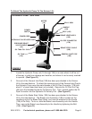
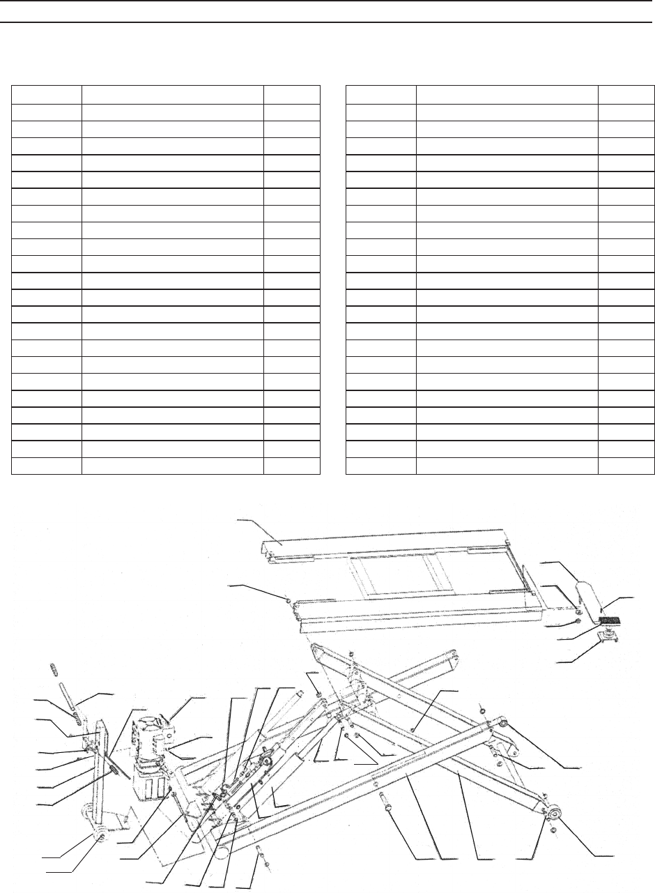
PARTS LIST/ASSEMBLY DIAGRAM B
REV 01/07
1B
2B
42B
41B
40B
39B
38B
43B
11B
16B
10B
12B
13B
14B
15B
16B
17B
18B
19B
20B
21B
22B
36B
35B
23B
24B 25B
26B
27B
28B
37B
30B
31B
32B
3B
4B
5B
6B7B
6B
8B
9B
29B
44B
45B
46B
Part #
Description Qty.
1B Table 1
2B Retaining Ring (18) 8
3B Locking Nut (M20) 1
4B Oil Pipe Connector (3) 3
5B Branch Inlet Pipe 2
6B Oil Pipe Connector (2) 2
7B Oil Supply Fitting 1
8B Nut (M8) 4
9B Washer (8) 4
10B Brake Steel Cable 4
11B Handle 1
12B Hex Screw (M8) 4
13B Brake Lever Assy. 1
14B Bolt (M8) 4
15B Transmission Holder 1
16B Rubber Cap 3
17B Oil Pipe Connector (1) 1
18B General Inlet Pipe 1
19B Check Valve 2
20B Safety Locking Pin 1
21B Retaining Ring (20) 20
22B Cylinder Pin 2
Part #
Description Qty.
23B Scissor Pin 2
24B Outer Scissor 1
25B Inner Scissor 1
26B Wheel Pin 2
27B Large Wheel 2
28B Small Wheel 2
29B Wheel Pin 2
30B Connecting Pin 2
31B Cylinder Pin 2
32B Safety Locking Pin 1
35B Cylinder Assy. 2
36B Safety Lock Assy. 1
37B Retaining Ring (24) 2
38B Saddle Holder 4
39B Rubber Saddle 4
40B Locking Nut 4
41B Washer (20) 4
42B Plate 4
43B Bolt (M8 x 20) 4
44B Ring (15) 2
45B Wheel 2
46B Nut 2


