SKU 91315 For technical questions, please call 1-800-444-3353. Page 11
response to the Brake Lever. Then, release pressure on the Brake Lever.
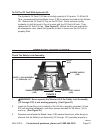
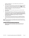
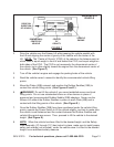
(See Figures D and E.)
Press on the Power Switch and hold, and observe that the Safety Lock Assembly
(1C through 11C) “clicks” into place as the Scissor Lift rises. NOTE: There are
safety catches on the Safety Lock Assembly as the Scissor Lift rises. Once the
Safety Lock Assembly locks into each of these safety catches, you must squeeze
and hold in on the Brake Lever (13B) to lower the Scissor Lift.
(See Figures D and E.)
Once the Scissor Lift is fully elevated, release pressure on the Power Switch.
(See Figure D.)
Without squeezing the Brake Lever (13B), press in on the Pressure Relief Valve
Handle (3A) and hold. Observe that the Scissor Lift will not lower, as the Safety
Lock Assembly (1C through 11C) is engaged. CAUTION! If the Safety Lock
Assembly does not engage, fully lower the Scissor Lift and have a qualied
service technician immediately repair the Safety Lock Assembly.
(See Figures D and E.)
Should the Safety Lock Assembly (1C through 11C) not operate as described
in Step #6, raise the Scissor Lift slightly to take pressure off the safety catches.
Then, while squeezing the Brake Lever (13B) lower the Scissor Lift fully to the
oor.
Note: When working properly, you must BOTH squeeze in and hold the Brake Lever
and press in and hold the Pressure Relief Valve Handle (3A) to lower the Scissor
Lift. (See Figure D.)
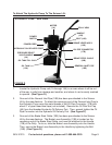
To Position, Lift, And Lower A Vehicle On The Scissor Lift:
Before driving a vehicle onto the Scissor Lift make sure that the Lift is fully
lowered, and position the Plates (42B) and Rubber Saddles (39B) inward.
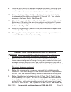
(See Figure E.)
4.
5.
6.
7.
1.


