SKU 91315 For technical questions, please call 1-800-444-3353. Page 12
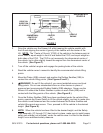
DRIVE-ON
DIRECTION
OF VEHICLE
DIMENSIONAL
CENTER OF
VEHICLE
CENTER
OF
GRAVITY
VEHICLE
ENGINE
UNDERNEATH
VEHICLE
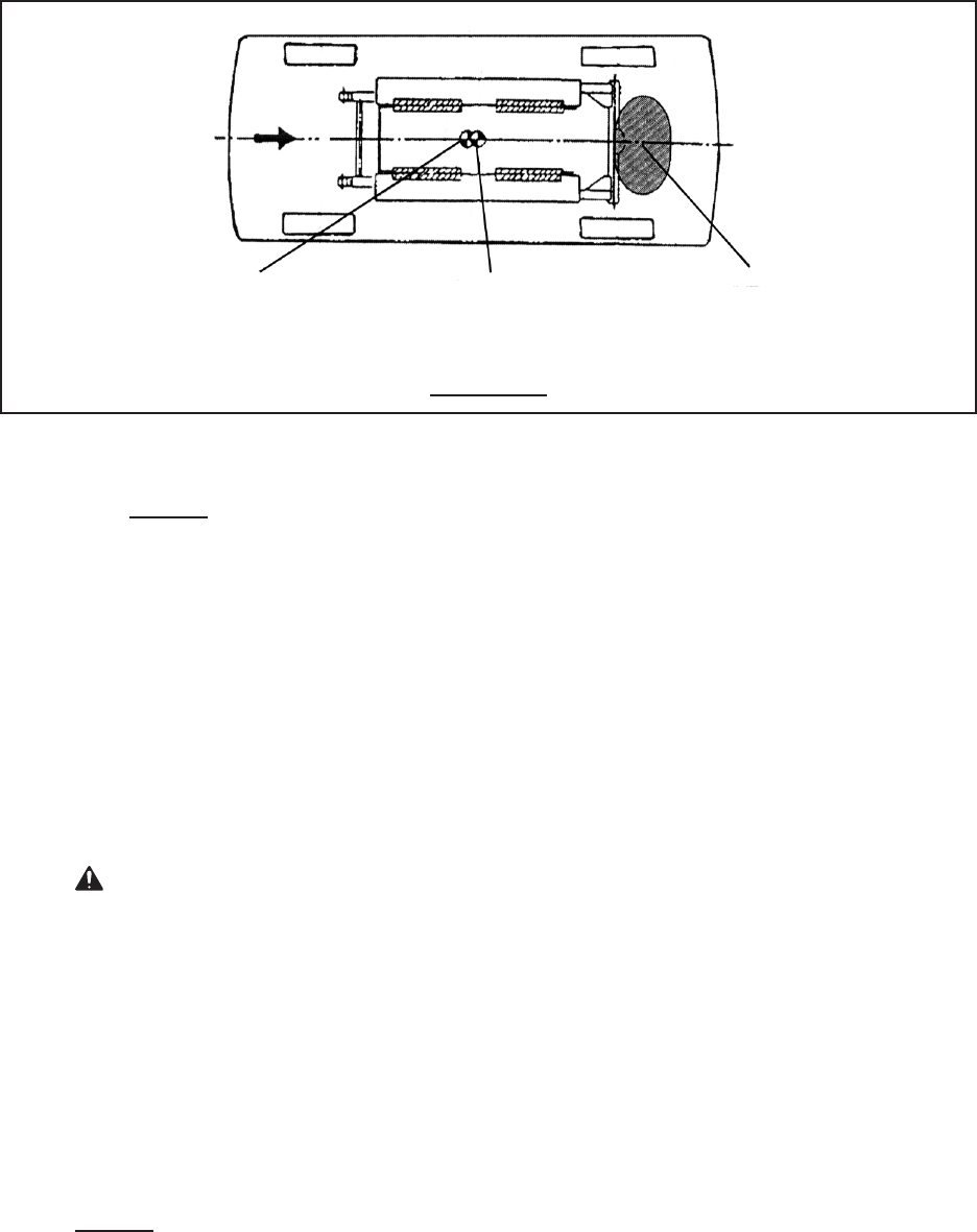
FIGURE F
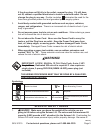
Drive the vehicle over the Scissor Lift while keeping the vehicle parallel with
the Lift and aligning the center of gravity of the vehicle with the center of the
Lift. NOTE: The “Center of Gravity” (COG) of the vehicle is the balance point at
which there is equal weight in front of and behind the COG, and equal weight on
both sides of the COG. The COG is not necessarily the dimensional center of
the vehicle, but is often slightly toward the engine from the dimensional center of
the vehicle. (See Figure F.)
Turn off the vehicle’s engine and engage the parking brake of the vehicle.
Read the vehicle owner’s manual to identify the recommended vehicle lifting
points.
Move the Plates (42B) outward, and position the Rubber Saddles (39B) to
contact the vehicle lifting points. (See Figures E and F.)
WARNING! Do not lift the vehicle if you cannot establish secure and level
lifting points. Do not use substandard shims or other devices in place of
approved and recommended Rubber Saddle (39B) adapters. Never use the
Scissor Lift without the Rubber Saddles in place on each Plate (42B) and in
contact with the lifting points of the vehicle. (See Figure E.)
Once the Rubber Saddles (39B) have been positioned under the vehicle lifting
points, operate the Power Switch to lift the vehicle slightly, and test to make sure
the vehicle is well balanced and the contact between the Rubber Saddles and
vehicle lifting points are secure. Then, proceed to lift the vehicle to the desired
height. (See Figure E.)
NOTE: When the vehicle has been lifted to the desired height, and the Safety
Lock Assembly (1C through 11C) has locked in place, make sure to install proper
safety jack stands (not included), under the vehicle once it is lifted to the desired
height, as an additional safety measure.
2.
3.
4.
5.
6.
7.
8.


