Eclipse User Manual
Release 1.10.1 Page 9 of 58 Eclipse User Manual
Out The Eclipse sends MIDI messages to other devices via the Out port.
MIDI messages are also sent out the serial port if they are “enabled.”
Thru Any MIDI information received at the MIDI In port is echoed di-
rectly to the MIDI Thru port regardless of the Eclipse’s configura-
tion
(as long as the Eclipse is powered up).
With the Memory Card removed, the BUSY LED on the front panel illuminates whenever a
MIDI message is received at the MIDI In port. Note: If the serial port is “enabled” and MIDI
is “enabled,” a command received over either the serial port or the MIDI In port causes the port
not receiving the command to be ignored until the command is complete.
! for MIDI Setup see page
43
K) Remote Power In
Power supplied at this jack is sent “down” the MIDI In port’s pins 6 and 7. Use a suitable
MIDI pedal board and connect its “wall wart” (external power supply) to this jack. Use a "7
pin" MIDI cable between the Out port on the board and the In port on the Eclipse. Power
will be remotely supplied to the MIDI pedal board.
L) Foot Pedal Jacks 1 & 2
Stereo 1/4-inch connectors. The sleeve is ground reference, the ring is a +5 volt (source),
and the tip is an analog signal from 0 to 5 volts. Connect either foot switches, foot pedals, or
control voltage sources to these inputs to modulate parameters or to trigger events (includ-
ing remote program loads, see page 43).
! To set up the foot pedal jacks, see page 44
Getting Around and Altering Parameters
At any given time, the Eclipse is doing a whole bunch of “stuff.” Unfortunately, you can’t look at all that
“stuff” at in one fell swoop.
We could have arranged things otherwise, but we figured you’d rather not devote twelve rack spaces to the Eclipse
display where you really only need one!
As a compromise, we’ve created a number of “windows” on its inner-workings.
We call them “areas.” Inside each area are parameters that can be selected by using the “soft keys” below
the display. Once a parameter is selected, you can alter its value with the knob or the keypad. Let’s look at
this in a little more depth, shall we?
The “Areas” (e.g. – Levels, Program, Setup, etc.)
Each area has a dedicated key and an LED that illuminates when you’re “in” that area. For example, press-
ing the
LEVELS key illuminates its LED and changes the display to show the LEVELS area parameters. Press
the
LEVELS key again to see even more parameters! Here’s a list of areas and the sorts of things you can
view in each:
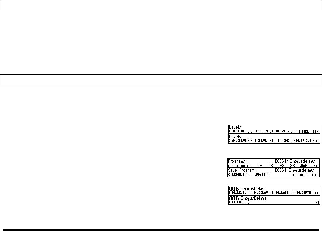
LEVELS Input and output levels at different points along the signal
path along with master wet/dry controls and coarse signal
flow controls.
! see page 18
PROGRAM Utilities for sorting, loading, and saving programs.
! see page 26
HOT KEYS
A real help for speedy sessions! All of the most important
parameters for factory programs are found here, and you
can assign parameters from any other area here for quick ac-
cess.
! see page 30


