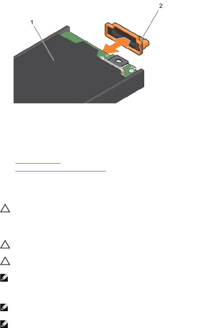
Figure 17. Removing and installing the I/O connector cover
1. storage sled 2. I/O connector cover
Next steps
Install the storage sled or sled blank.
Related Links
Safety instructions
Storage sled mapping configurations
Installing a storage sled
Prerequisites
CAUTION: Many repairs may only be done by a certified service technician. You should only
perform troubleshooting and simple repairs as authorized in your product documentation, or as
directed by the online or telephone service and support team. Damage due to servicing that is
not authorized by Dell is not covered by your warranty. Read and follow the safety instructions
that came with the product.
CAUTION: To prevent damage to the I/O connectors, do not touch the connectors or the
connector pins.
CAUTION: To prevent damage to the sled locks, use a #2 Phillips screwdriver to turn the sled
locks to lock or unlock positions.
NOTE: Install the storage sleds in the bottom slots of the PowerEdge FX2s enclosure, beginning
from the left (slot 3). In the four-bay chassis, you can also install a storage sled in the top right slot
(slot 2) of the enclosure. For more information on sled slot numbering, see the
Dell PowerEdge FX2
and FX2s Enclosure Owner's Manual at dell.com/poweredgemanuals.
NOTE: If your storage sled has shipped pre-installed in the enclosure, it is recommended that you
remove the sled before installing the enclosure in the rack, to reduce chassis weight.
NOTE: If you are installing the storage sled in an enclosure that is already powered on, you need not
turn off the enclosure to install the storage sled. Only the compute sled(s) to which the storage sled
is mapped must be turned off.
1. Ensure that you read the Safety instructions.
2. Turn off the compute sled to which the storage sled is mapped, by using the CMC, iDRAC, or the
power button on the compute sled.
20


