


INSTALLATION DIRECTIVE
9
V08 ENT M75
-
M11
-
M12
MAY 2006
05_009_V
5
1
7
11
10
8
9
6
32
4
12
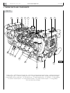
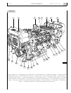
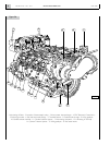
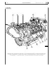
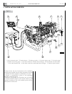
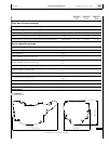
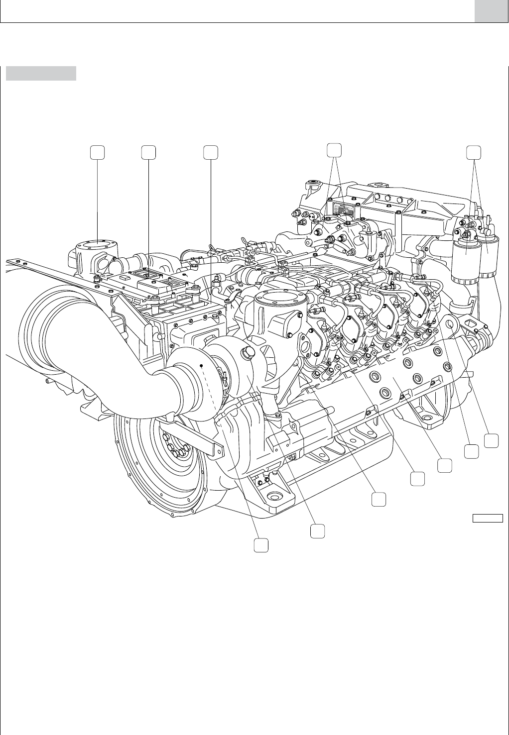
Figure 2B
1. Exhaust gas outlet - 2. EDC Electronic Central Unit - 3. Air-sea water heat exchanger - 4. Location of thermostatic valves -
5. Fuel filters - 6. Lifting padeyes - 7. Cylinder 1 electro-injector - 8. Cooled exhaust manifold - 9. Cylinder 4 electro-injector -
10. Lifting padeyes - 11. Cooled turbo-charger - 12. Sacrificial anode (placed on the air/water heat exchanger).