


INSTALLATION DIRECTIVE
16
V08 ENT M75
-
M11
-
M12
MAY 2006
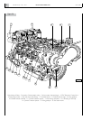
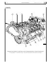
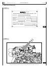
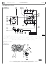
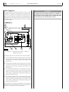
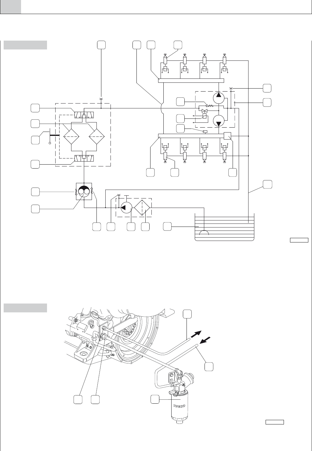
Fuel supply system scheme
Figure 8
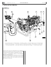
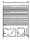
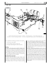
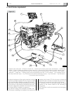
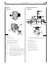
Hydraulic connections
Figure 9
1. Vent fitting - 2. Compensation duct between two rails - 3. Common rail - 4. Electro-injector - 5. Low pressure limiter valve -
6. Vent fitting - 7. Twin-cylinder high pressure pump - 8. Pressure control solenoid valve - 9. Pressure sensor - 10. Common rail
overpressure valve - 11. Low pressure recirculation duct - 12. Fuel tank - 13. Prefilter - 14. Manual priming pump - 15. Vent fitting -
16. Recirculation valve for low pressure pump - 17. Low pressure mechanical feed pump - 18. By-pass valve for low pressure pump -
19. Lever for switching filters - 20. Fuel filters - 21. Filter exclusion valves.
1. Fitting for fuel outflow to the tank - 2. Fitting for for fuel inflow from prefilter - 3. Prefilter -
4. Fuel inlet pipe from the tank - 5. Fuel return pipe to the tank.
05_014_V
1
6
15
12
14 13
3 4 10
7
16
3 42
11
19
20
18
17
5
8
9
21
21
3
1 2
5
4
05_015_V