


INSTALLATION DIRECTIVE MAY 2006
30
V08 ENT M75
-
M11
-
M12
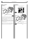
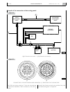
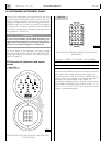
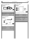
The connection is achieved by removing the cap on the JE
connector of the main panel, and connecting the JE connec-
tor to the JH connector on the secondary panel, interposing
the extension wire harness, available in 3, 5 and 7 metre-long
versions (see Fig. 19). The JE-JH wire harness comprises 12
lines, each connected to the terminal identified on both con-
nectors by the same number (see fig. 24).
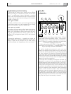
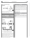
CONNECTORS OF THE JE-JH EXTENSION WIRE
HARNESS, SEEN FROM THE COUPLING SIDE
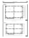
Installation
In order to drill holes on the area where the panel is to be
mounted, refer to the dimensions indicated in Chapter 11.
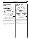
Operation of the secondary panel
After completing the electrical connection to the main panel
and engine preparation, and performing the tests required
for the first start (as described in Chapter 18), verify the
proper operation of the panel, proceeding as follows:
o Make sure that the “ENGINE ROOM / BRIDGE” switch
of the Relay Box is in the “BRIDGE” position, then turn
the key switch to the first position, thus enabling the
operation of both panels.
o Carry out the same tests for the secondary panel as
were carried out for the main panel.
o Disable the secondary panel by bringing the key switch
on the main panel to the resting or zero position.
Testing the engine start and stop function.
With the panel enabled, press the green push-button until
the engine starts, then release it; wait for engine rpm to sta-
bilize before stopping it by pressing the red push-button.
The starting and stopping operations can be performed sev-
eral times and consecutively from the secondary panel
Checking indications
Proceed in the same way as for the main panel.
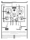
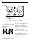
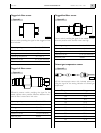
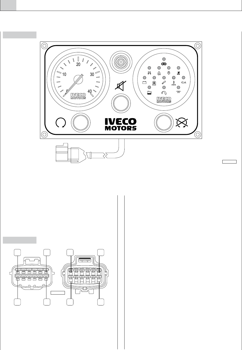
10. SECONDARY ANALOG INSTRUMENT PANEL
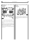
Figure 29
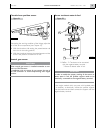
Figure 28
1.Connector for secondary panel wire harness (JH) - 2. Engine start push-button (CS) - 3. Revolution-counter (CG) -
4. Buzzer (SA) - 5. Indications and alarms module (MS) - 6. Engine stop push-button (AS) -
7. Sound alarm inhibition push-button (P1).
*% *(
1 6 6 1
7 12 12 7
electronic
RPMx100
04_240_N
04_251_N