


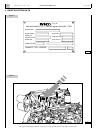
INSTALLATION DIRECTIVE MAY 2006
10
V08 ENT M75
-
M11
-
M12
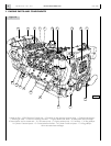
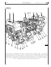
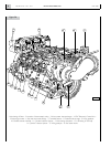
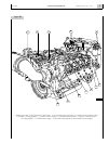
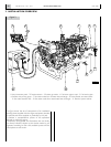
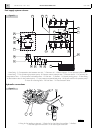
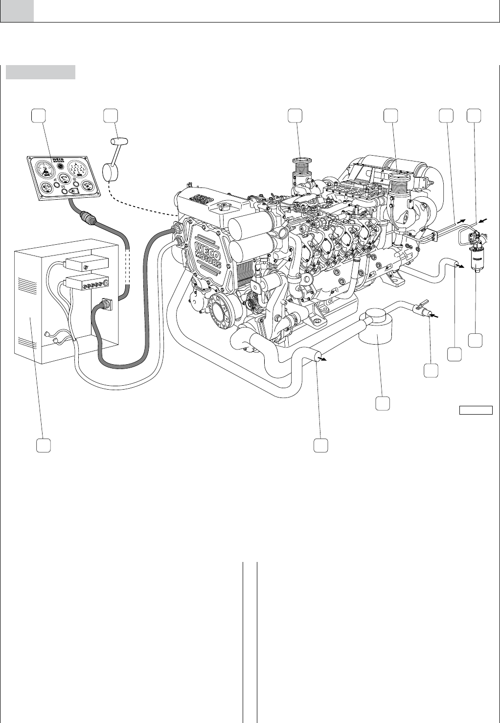
3. INSTALLATION OVERVIEW
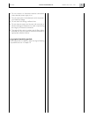
Figure 3
The figure shows the set of components of an installation,
including those supplied with the engine equipment, standard
or optional, and those supplied or produced by the yard.
It provides a comprehensive picture of the operations
required to install the engine.
Components arrangement and illustrations are not binding
but merely indicative, subject to the choices made by yard
engineers according to their skills, available spaces and the
prescriptions set out herein.
05_003_V
1 2 3 4 5
6
7
8
9
1011
3
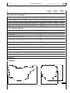
1. Main instrument panel - 2. Throttle actuator - 3. Exhaust gas outlet - 4. Fuel return pipe to tank - 5. Fuel suction pipe -
6. Prefilter with priming pump - 7. Sea water outlet from air/water heat exchanger - 8. To the filtered sea water intake -
9. Sea water decanter filter - 10. Sea water outlet from water/water heat exchanger - 11. Electrical system cabinet.