INSTALLATION DIRECTIVE
33
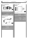
V08 ENT M75
-
M11
-
M12
MAY 2006
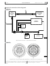
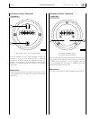
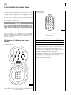
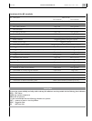
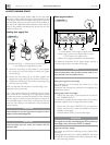
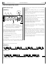
Functions of the JD terminals
PIN Description Electric level
OFF Indication ON Indication
1 Module power supply Positive (+B)
2 Not connected -
3 EDC Fault indication High (+B) Low (ground)
4 Not connected -
5 Pre-heating indication High (+B) Low (ground)
6 Pre-lubrication indication Open circuit High (+B)
7 Engine start Power supply positive (+B) while starting
8 Buzzer inhibition Negative (ground) during the request
9 Module power supply Negative (ground)
10 Sound alarm power supply Negative (ground) during the emission of sound
11 Clogged oil filter indication Open circuit Low (ground)
12 Clogged oil vapour filter indication (not applicable) Open circuit Low (ground)
13 Clogged air filter indication Open circuit Low (ground)
14 Clogged fuel filter indication Low (ground) Open circuit
15 Alternator fault indication High (+B) Low (1 to 3 V)
16 Low engine coolant level indication Open circuit Low (ground)
17 High coolant temperature indication Open circuit Low (ground)
18 Low engine oil pressure indication Open circuit Low (ground)
19 Presence of water in fuel indication Open circuit Low (ground)
20 Overloaded or runaway engine indication Open circuit High (+B)
21 Not connected -
22 Not connected -
23 Reception of data from main panel NMEA communication protocol (0 to 5 V)
24 Transmission of data to secondary panel NMEA communication protocol (0 to 5 V)
CAUTION
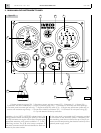
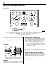
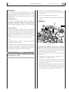
To assure the utmost reliability and safety while underway, all installations must be provided with the following alarm indications:
(EDC) EDC failure
(SATA) high coolant temperature
(SBPO) low oil pressure
It is also recommended that the following indications are present:
(SAC) presence of water in the fuel prefilter
(SIFA) clogged air filter
(SS) alternator fault


