


INSTALLATION DIRECTIVE MAY 2006
38
V08 ENT M75
-
M11
-
M12
16. FIRST ENGINE START
Before starting the engine, please make sure the sea water
gate valve is open, check the levels of the lubricating oil and
of the engine coolant, and complete venting the air from the
fuel feed loop, acting on the hand pump of the prefilter or
with the aid of a dedicated electrical pump. Loosen the vent
fitting on the prefilter and operate the pump until only fuel
without air flows out.
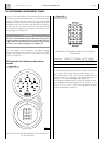
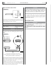
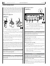
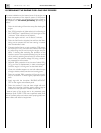
Venting fuel supply line
1. Prefilter vent fitting - 2. Vent fitting on the filter support -
3. Vent fitting on the high pressure pump.
o Loose the vent fitting on the prefilter (1) and operate
the pump until only fuel without air flows out. Tighten
the vent fitting.
o Loosen the vent fitting (2) on the filter support and
operate the pump until only fuel without air flows out.
o Tighten the vent fitting (2) and continue pumping during
the initial start-up phases.
Make sure that the fuel that flows out of the fitting is not
dispersed in the environment.
Only if the engine starting is very difficult, stop the engine,
insert a hose on the vent fitting of the high pressure pump
(3), loose the junction and start the engine for a few seconds.
Stop the engine, remove the hose and tight the junction to
the prescribed torque value. Make sure that the fuel that
flows out of the fitting is not dispersed in the environment.
Start the engine.
CAUTION
Never attempt to vent the high pressure system as this is
useless and extremely dangerous.
CAUTION
Avoid accurately that fuel comes into contact with the
alternator belt.
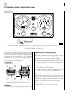
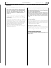
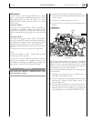
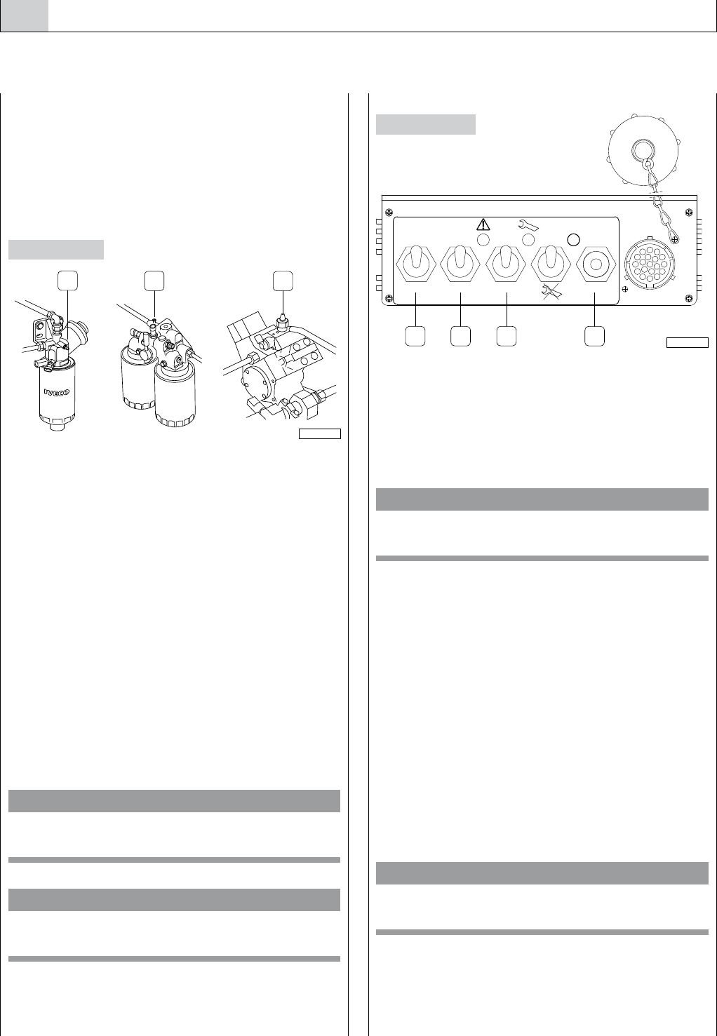
Start-up procedures
1. Control selector from bridge or engine room -
2. Power supply switch of the engine electric circuits -
3. Start button from engine room -
4. Button for managing acceleration and deceleration.
The electrical equipment of this engine allows starting it
from the “engine room” and from the “bridge”.
NOTE
A few moments after start-up, make sure sea water is cor-
rectly drained from the relevant circuit.
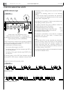
Starting the engine from the bridge
This is allowed only if the Relay box switch (1) is in the
“BRIDGE” position.
Procedures and warnings are provided in the operation and
maintenance manual.
Starting engine from the “bridge”
- Switch over the switch (1) of the relay box in the posi-
tion “ENGINE ROOM”.
This operation excludes all the bridge controls and must be
absolutely avoided when the engine has been started.
- Switch over the switch IGNITION (2) to power the
electric circuits of the system and enable the controls
available on the panel.
- Press the button START (3) to start the engine.
WARNING
The engine start is fully controlled by the ECU; the start-up
phase begins when the button START is released.
Engine shut-off from “bridge”
The engine shut-off occurs switching over the switch IGNI-
TION (2).
Bringing again the switch (1) in position “BRIDGE”, the use of
the controls will be disabled on the Box, enabling the start-
up only the bridge controls.
Figure 44
Figure 43
05_016_V
1
2
3
"2)$'%
2//-
)'.)4)/. 34!24 20-
20-
%.').%
#(%#+
1 32 4
05_007_V