INSTALLATION DIRECTIVE MAY 2006
48
V08 ENT M75
-
M11
-
M12
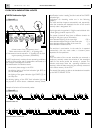
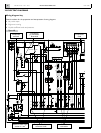
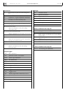
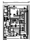
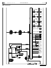
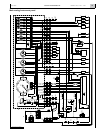
Connectors
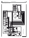
J1 on the relay box panel for external diagnostic
tool
J1 70-pole EDC - boat components connections
J2 70-pole EDC - engine components connections
J3 lubrication oil transfer electrical pump
J4 pre-lubrication electrical pump
JA connection between engine wiring and interface
wire harness
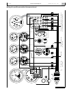
JB ON ENGINE WIRE HARNESS
ready for connection to the main analog
instrument panel
JC ON MAIN ANALOG INSTRUMENT PANEL
ready for connection to the engine wire harness
JD IVECO MOTORS indications and alarms module
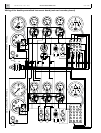
JE ON MAIN ANALOG INSTRUMENT PANEL
ready for connection to the secondar y
analog instrument panel
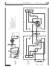
JF1,JF2 relay box
JH ON SECONDARY ANALOG INSTRUMENT PANEL
ready for connection to the main analog
instrument panel
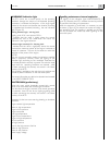
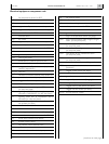
Indicator lights
EDC EDC malfunction
SAC presence of water in fuel prefilter
SATA coolant high temperature
SBLA low coolant level
SBPO low oil pressure
SCP pre-post heating
SIFA clogged air filter
SIFB clogged oil vapour filter
SIFC clogged fuel filter
SIFO clogged oil filter
SIM expired programmed maintenance interval
SP pre-lubrication
SS alternator fault
SSV engine overspeed
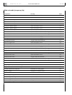
Gauges
CG revolution-counter
MI gear box oil pressure
MO engine oil pressure
TA engine temperature
TI gear box oil temperature
TS exhaust gas temperature
V voltmeter
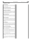
Relays contained in the relay box
K1 key switch electric discharge
K2 IGNITION switch electric discharge
K3 power supply to terminal 50 of the electric
starter motor
K4 start request signal, from key switch to EDC
electronic unit
K5 TGC control ready
KR EDC blink code emission LED control
Fuses contained in the relay box
F1- F2 self restoring (not replaceable)


