


FirstGPS Starter Kit User Guide
11
FirstGPS Starter Kit Overview
1
1.3.2
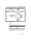
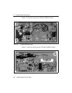
Motherboard
The MPM interface motherboard includes a +9 to +32 VDC input
software switching power supply that provides a regulated +3.3 VDC
to the MPM receiver. It also converts the TTL level I/O to RS-232 for
a direct interface to the computer. The motherboard provides an open
collector interface for the PPS. The input voltage must be between
+9 VDC and +32 VDC and is input to the board through a 3-pin
circular connector of which only two pins are used. Supplying power
outside the specified input range will damage the board.
Although there are two communication ports on the motherboard, only
one is available for use by the MPM (Port 1).
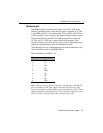
The pin identities for PORT 1 are:
Note – Due to the open-collector interface, through the 9-pin RS-232
port, the polarity of the PPS signal is inverted. The pulse is a 4
µ
s
negative-going pulse with the falling edge synchronized to UTC. When
removed from the motherboard, the receiver provides a positive-going
TTL level pulse, with the rising edge synchronized to UTC.
Pin # Function
1 NC
2 TX
3 RX
4 NC
5 GND
6 NC
7 NC
8 NC
9 PPS