


page 9
Installation
SECTION 2
This section contains the necessary steps to assist in getting a new flowmeter in operation as quickly
and easily as possible. Please read the following thoroughly before attempting to install the instru-
ment.
WW
WW
W
ARNINGARNING
ARNINGARNING
ARNING
The customer should determine if their process gas is compatible withThe customer should determine if their process gas is compatible with
The customer should determine if their process gas is compatible withThe customer should determine if their process gas is compatible with
The customer should determine if their process gas is compatible with
thethe
thethe
the
wetted materials of the flowmeter as specified in section 1.2. Somewetted materials of the flowmeter as specified in section 1.2. Some
wetted materials of the flowmeter as specified in section 1.2. Somewetted materials of the flowmeter as specified in section 1.2. Some
wetted materials of the flowmeter as specified in section 1.2. Some
corrosivecorrosive
corrosivecorrosive
corrosive
gases may damage the flowmeter materials and elastomergases may damage the flowmeter materials and elastomer
gases may damage the flowmeter materials and elastomergases may damage the flowmeter materials and elastomer
gases may damage the flowmeter materials and elastomer
O-rO-r
O-rO-r
O-r
ing.ing.
ing.ing.
ing.
This could result in incorThis could result in incor
This could result in incorThis could result in incor
This could result in incor
rect florect flo
rect florect flo
rect flo
w measurement,w measurement,
w measurement,w measurement,
w measurement,
or leakage o or leakage o
or leakage o or leakage o
or leakage o
vv
vv
v
erer
erer
er
time.time.
time.time.
time.
2.1 Receiving and Inspection
Carefully unpack the Hastings HFM-60 and any accessories that have also been ordered. Inspect
for any obvious signs of damage to the shipment. Immediately advise the carrier who delivered the
shipment if any damage is suspected. Check each component shipped with the packing list. Insure
that all parts are present (i.e., flowmeter, wall transformer power supply, cables, etc.). Optional
equipment or accessories will be listed separately on the packing list. There may also be one or
more OPT-options on the packing list. These normally refer to special ranges or special gas
calibrations. They may also refer to special helium leak tests, high pressure tests or special modifi-
cations such as high temperature O-ring materials. In most cases, these are not separate parts, but
special options or modifications built into the flowmeter.
2.2 Power Requirements
The HFM-60 requires +15 to+25VDC, 60mA (0 - 5VDC output); 80mA (4 -20mA output). The
supply voltage should be regulated such that there is no more than 50 mV ripple. Surge suppres-
sors are recommended to prevent power spikes reaching the instrument. These power require-
ments are satisfied by the Hastings wall transformer or by the Hastings wall power supply described
in Section 1.6.1 or 1.6.2.
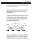
2.3 Output Signal
The standard output of the flowmeter is a 0-5 VDC signal proportional to the flow rate. The input
power is applied at pins 1 (+15 to+25 VDC) and 2 (ground). The output is obtained on pins 3 (0 to
+5 VDC) and 4 (common) of the 4 pin connector. It is recommended that the load resistance be
no less that 2 kΩ. When the 4-20 mA option (see Section 1.3) is selected the output is also on pins
3 and 4. The load impedance must be no greater than 400 Ω.
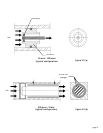
2.4 Mechanical Connections
The flowmeter may be mounted in any position as long as the direction of gas flow through the
instrument follows the arrow marked on the bottom of the flowmeter case label. The preferred
orientation is with the inlet and outlet fittings in a horizontal plane. Changing the mounting
orientation requires re-zeroing of the instrument at zero flow.
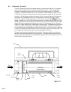
The smallest of the internal passageways in the HFM-60 is the diameter of the sensor tube, which
is 0.020 and the annular clearance for the 500 sccm shunt which is 0.009", so the instrument
requires adequate filtering of the gas supply to prevent blockage or clogging of the tube. The
screen diffusers assist in filtering to some extent where the filter mesh is as small as 0.010".