


page 13
Theory of Operation
SECTION 3
This section contains an overall functional description of the HFM-60. Detailed schematics and
parts lists can be found at the end of the manual in Section 5.0. In this section and other sections
throughout this manual, it is assumed that the customer is using the wall transformer power supply
supplied by Hastings or a Hastings Power Supply.
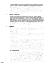
3.1 Overall Functional Description
The HFM-60 consists of a sensor, a base, shunt and electronic circuitry. The sensor measures the
gas flow rate from 0 to 10 sccm. The shunt divides the flow such that the flow through the sensor
is a precise percentage of the flow through the shunt. The flow through both the sensor and shunt
is laminar. The circuit board amplifies the sensor output from the two Chromel P thermocouples
and and provides an analog output of either 0-5 VDC or 4-20 mA. The output can also be
indicated on the digital display.
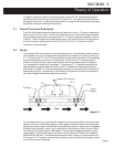
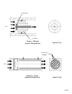
3.2 Sensor
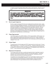
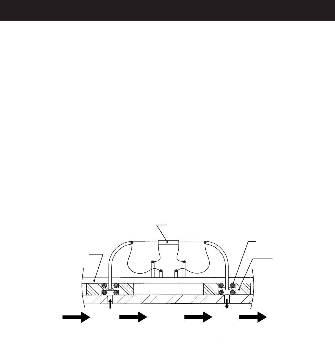
The Hastings HFM-60 operates on a unique thermal electric principle whereby a metallic capillary
tube is heated uniformly by a resistance winding attached at the center of the capillary (see figure
3.1). Thermocouples TC-1 and TC-2 are positioned on each side of the heater coil and are welded
at equal distances from the mid-point of the capillary. At zero flow, the TC outputs are equal.
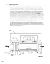
When flow occurs through the tubing, heat is transferred from the heated region to the gas and
from the gas back to the cool wall downstream. Thermocouple TC-1 measures the temperature
upstream before the gas is heated and thermocouple TC-2 measures the gas temperature down-
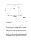
stream after it is heated. During flow, the temperature distribution along the sensor tube becomes
skewed (see figure 3.2). Conventionally, the difference in temperature of the two thermocouples
provides a voltage difference that is proportional to flow.
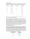
For a constant power input, the differential voltage is a function of the mass flow rate and the heat
capacity of the gas. Since the heat capacity of many gases is relatively constant over wide ranges
of temperature and pressure, the flowmeter may be calibrated directly in mass units for those gases.
Changes in gas composition usually require application of a multiplication factor to the air calibra-
tion to account for the difference in heat capacity. The flowmeter is capable of measuring a wide
range of gases. The Monel 400 sensor tube has an internal diameter of 0.0205" and is heated by
600 W of MWS-800 wire. This diameter allows approximately 10 sccm full scale flow with ∆p of
0.5 inches of H
2
O. The sensor is encapsulated by a plastic cover and filled with fiberglass insulation
to minimize convective heat losses.
Heater (VDC Source)
TC-1
TC-2
Nylon
Spacer
O-ring
PC Board
flow
figure 3.1