


page 16
3.5 Electronic Circuitry
The HFM-60 employs a thermal flow sensor (capillary tube described in section 3.2) to measure
the flow which is proportional to the total flow through the instrument. The sensor develops a
differential voltage output signal proportional to flow which is approximately 1 mV full scale
magnitude. A differential amplifier and an inverting amplifier boost the signal strength by a factor
of ~5000 at full scale flow. The amplified output can be measured on pins 3 and 4 of the external
connector. If a Hastings power supply is employed, the 5 volt output is also sent to the terminals
on the back and to the decoding circuitry in the display which converts it to a 3 and 1/2 digit
output. An optional 4-20 mA analog output on pins 3 and 4 is also available
in lieu ofin lieu of
in lieu ofin lieu of
in lieu of an output
voltage. The addition of a 4-20 mA current loop transmitter on the secondary pc board (mounted
parallel to the main pc board) is required to provide this current loop. A jumper change is made on
the main PC board to establish the selected output mode. The digital display option includes the
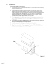
tiltable LCD display module which is removable for remote display. This separate module contains
its own pc board and mounts directly on the top of the main cover. This local or remote digital
unit provides a continual digital display in addition to the 0-5 VDC or 4-20 mA output. A standard
4 conductor phone jack and cable is used to connect the display module to the main pc board. The
circuit diagrams for the aforementioned functions are presented in Section 6.
This section contains service and calibration information. Some portions of the instrument are
delicate. Use extreme care when servicing the instrument. The potentiometer positions and the
electrical components referred to in the troubleshooting section can be found in Section 4.3 on the
electrical component layout drawing.
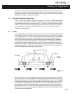
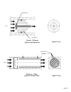
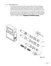
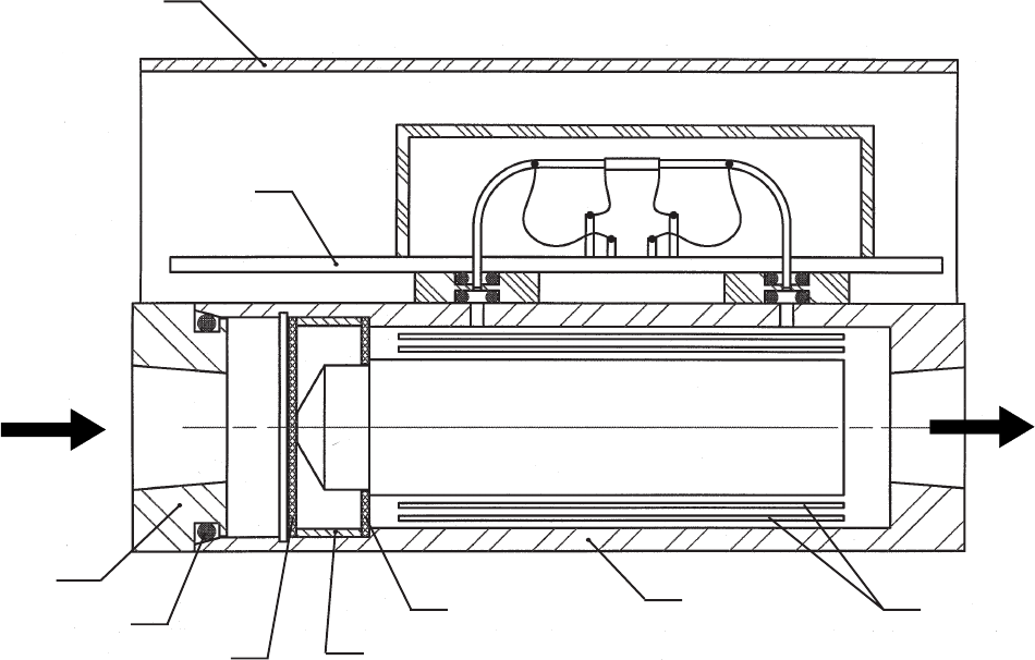
flow
end cap
O-ring
coarse
screen
fine
screen
base
shunt plug
(60 slm shown)
shunt
tubes
PC
board
cover
spacer
figure 3.4