


page 14
3.3 Base
The 6061 aluminum alloy base has a 1" square cross-section and is 3.375" long (with end cap).
The internal flow channel is 0.812" diameter with in and out 304L stainless steel fittings 1/4" NPT
to 1/4" Swagelok fittings.
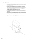
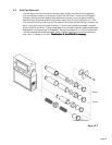
3.4 Shunt
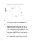
The flow rate of interest determines the size of the shunt required. As previously indicated, 13
separate shunts are required for the range of flow spanning 10 sccm to 70 slpm full scale. The
geometry of the shunt for 0- 200 sccm is shown in figure 3.3(a). Four Monel 400 tubes of 0.027"
i.d. are located within the aluminum plug to accommodate the full 200 sccm. Lower flow rates
require proportionally fewer tubes and the unused holes are sealed with epoxy (or selected eutectic
solder if epoxy is undesired). At the lowest flow rate (10 sccm), the shunt is completely blocked and
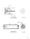
all of the flow is routed through the sensor. Figure 3.3(b) shows the geometry for higher flow rates.
A single 304L stainless steel plug with an annular spacing of 0.009" accommodates the 500 sccm flow
range. Increasing the flow requires more annular passageways which is accomplished by adding
concentric cylinder shells with increasing gap dimensions. Eventually, a maximum annular gap
dimension for laminar flow is obtained (~0.030"). For a maximum flow rate of 70 slpm, three
annular regions using two brass concentric cylinders is required. This patent pending shunt technol-
ogy also includes inboard sensor ports which ensure laminar flow without the turbulence associated
with end effects. This unique flow geometry provides an exceedingly linear shunt.
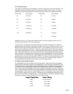
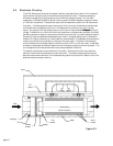
A schematic diagram of the integral flowmeter (without the digital display module) employing a 70 slpm
shunt is shown in figure 3.4. Note the inboard location of the sensors inlet and outlet with respect to
the inlet and outlet of the shunt. Also note the screen disk and washer which are used to minimize the
radial velocity gradient entering the shunt. This results in a more uniform flow velocity profile and
therefore, more uniform flow in the annular passages of the shunt.
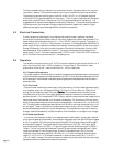
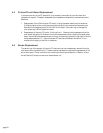
figure 3.2
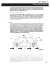
Length of tube
L/2 L/20
Temperature of
tube
TC-1 TC-2
ZERO
FLOW
SMALL
FLOW