


page 18
4.3 Adjustments
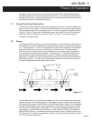
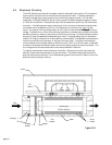
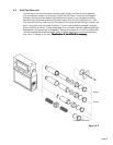
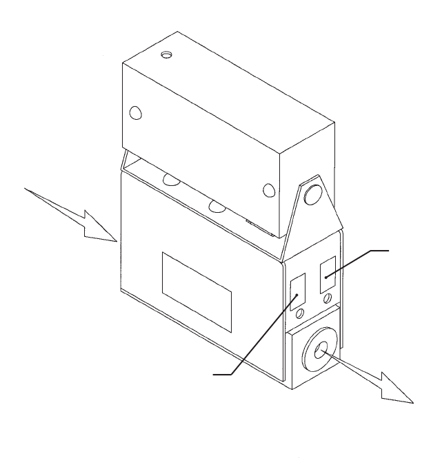
Calibration Procedure (See figure 4.1)
1. Connect power to pins 1 and 2 as specified in Section 2.5. Allow the instrument to warm up
for 30 minutes with 10% flow.
2. Completely shut off the flow and wait for 2 minutes. For the standard 0-5VDC output,
adjust the zero potentiometer located on the lower outlet side of the flowmeter until the
meter indicates zero. For the optional 4-20 mA output, adjust the zero potentiometer so that
the meter indicates slightly more than 4 mA, i.e. 4.03 to 4.05 mA. This slight positive
adjustment ensures that the 4-20 mA transmitter is not in its cut-off region. The error
induced by this adjustment is approximately 0.3% of full scale.
3. Turn on gas supply to inlet of instrument and insure the flow rate is an accurate maximum
flow for the shunt employed. Ensure that the full range can still be obtained at minimum
inlet pressure.
4. Adjust Span pot until the flow reference reads full scale (5.00VDC or 20 mA). Perform this
step only if a calibrated reference flowmeter is available.
5. Adjust the span pot of the display so that it reads correct full scale flow.
6. Record flowmeter and flow reference outputs for flow rates of 20%, 40%, 60%, 80% and
100% and make sure data are within ± 3% of full scale.
figure 4.1
span
zero
flow