


page 20
4.5 Printed Circuit Board Replacement
In the event that any of the PC boards fail, they are easily removed from the instrument and
replaced with a spare. This ease in disassembly and replacement substantially reduces instrument
downtime.
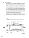
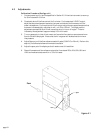
1. Replacement of the 4-20 mA option PC board: Unplug the power cable from the transducer.
If a digital display exists, unplug the phone jack connection and remove the flowmeter cover.
Remove the 4 brass spacers and lift off the 4-20 mA board. Be careful not to damage the
main board and 4-20 mA board connector.
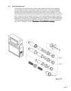
2. Replacement of the main PC board: Continue from 1. Remove the 4 brass spacers from the
main board and gently lift the board from the flowmeter base. When installing the replacement
board, insure that the brass spacers are uniformly and securely tightened (finger tight) since the
compression seals the “O”-rings on the base, PC board and the sensor tube which, in turn,
maintains the integrity of the flow in the sensor.
4.6 Sensor Replacement
The sensor is an intimate part of the main PC board and can not be separately removed from the
main board without great difficulty. Therefore, sensor replacement requires the replacement of the
entire main board. Follow instructions for removing the main board as shown in Section 4.5 and
consult Section 5 to acquire a new main board/sensor unit.