


page 7
1.3 Optional 4-20 mA Current Output
An option to the standard 0-5 VDC output is the 4-20 mA current output that is proportional to
flow. The 4 - 20 mA signal is produced from the 0 - 5 VDC output of the flowmeter. The current
loop output is useful for remote applications where pickup noise could substantially affect the
stability of the voltage output. The load impedance should be between 0 and 400 Ω.
1.4 Digital Display (0-90° Tiltable)
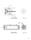
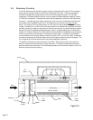
1.4.1 Local Display
For real time indication of the flow rate, a very useful option available is a 3.5 digit LCD digital
display module mounted directly on top of the flowmeter case. The display can be rotated 90°
from the horizontal position to the fully vertical for better visibility. The LCD digits are large and
clear and can be easily discerned at distances of 20 feet.
1.4.2 Remote Display
The tiltable display module may be removed from the flowmeter case and mounted at any distance
away from the flowmeter body to permit convenient observation. Standard lengths of 7', 15' and
25' cable (also special orders of any desired length) are available.
1.5 Wall Transformer Power Supply
The input voltage required for operation of the flowmeter is +15 to +25 VDC, at a maximum of
60 mA (80 mA for the 4-20 mA output option). A 115 VAC wall power supply rectified to +18.5
VDC is available as a power supply option. The wall power supply comes with a 6' length of 2
conductor cable which can be connected directly to the HFM-60 connector.
1.6 Other Accessories
1.6.1 Totalizer (ATR-1J)
The Hastings Flow Totalizer integrates the 0-5 VDC signal generated by the flowmeter to give a
total flow reading. Count rates from 0 to 999 counts per minute are selectable by internal setting.
1.6.2 Hastings Model 400/200/40/10 Power Supply
Hastings power supplies (other than the aforementioned wall transformer) are available in either
one, two or four channel versions. They convert 115 or 230VAC to the +15 VDC required to
operate the flowmeter. Interface terminals for the +15 VDC input and the 0-5 VDC linear output
signal are located on the rear of the panel. Also, a cable can be supplied with the power supply that
provides the +15 VDC on pin 11 of a “D” connector and the 0 - 5VDC output measurement on
pin 6. Pins 5 and 12 are common and pin 7 is chassis ground. Throughout this manual, when
reference is made to a power supply, it is assumed the customer is using a Hastings wall power
supply or a Model 200/400/40/10 supply.