


page 10
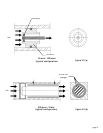
There is a threaded hole in the bottom of the transducer that can be used to secure it to a mount-
ing bracket, if desired. Other holes for special mounting can be added to the end cap as desired.
The standard inlet and outlet fittings for the HFM-60 are 1/4" NPT to 1/4" Swagelok (optional
VCR and VCO fittings are available from the factory). The O-rings for the end cap and the sensor
are Buna N (optional Kalrez, Neoprene or Viton O-rings are available from the factory). It is
suggested that all connections be checked for leaks after installation. This can be done by pressuriz-
ing the instrument (do not exceed 150 psig unless the flowmeter is specifically rated for higher
pressures) and applying a diluted soap solution to the flow connections.
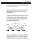
2.5 Electrical Connections
If a wall transformer power supply from Hastings Instruments is used, installation consists of
connecting the 4 conductor cable to the 4 pin connector located on the side of the flowmeter. The
power is supplied to the instrument on pin 1, +15 to +25VDC, and pin 2, ground. The output is
measured on pin 3, 0 - 5 VDC or 4-20 mA and pin 4, ground. If a Hastings Model 400/200/40/10
power supply is used, installation consists of connecting a 4 conductor cable to the terminal strip on
the rear of the supply to the 4 pin connector located on the side of the flowmeter (similar to that
described above). Also, a cable with a male “D” connector can be supplied that mates with the
power supply. The “D” connector cable provides +15 VDC on pin 11 and the 0-5 VDC output on
pin 6. Pins 5 and 12 are common and pin 7 is chassis ground.
2.6 Operation
The standard instrument output is a 0 - 5 VDC out and the signal is proportional to the flow i.e., 0
volts = zero flow and 5 volts = 100% of rated flow. The low noise 4 - 20 mA option is also
proportional to flow (4 mA = zero flow and 20 mA = 100% of rated flow).
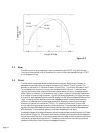
2.6.1 Operating Temperature
For proper operation, the combination of ambient temperature and gas temperature must be such
that the flowmeter temperature remains between 0 and 50°C. Most accurate measurement of flow
will be obtained if the flowmeter is zeroed at operating temperature as temperature shifts result in
some zero offset.
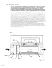
2.6.2 Zero Check
Connect the wall transformer power supply to the instrument or if using a Hastings power supply,
turn the power supply on. Allow approximately 10% flow for 1/2 hour warm-up. Stop all flow
through the instrument and wait 2 minutes.
Caution:Caution:
Caution:Caution:
Caution: Do not assume that all metering valves
completely shut off the flow. Even a slight leakage will cause an indication on the meter and an
apparent zero shift. For the standard 0-5 VDC output, adjust the zero potentiometer located on the
lower outlet side of the flowmeter until the meter indicates zero. For the optional 4-20 mA output,
adjust the zero potentiometer so that the meter indicates slightly more than 4 mA, i.e. 4.03 to 4.05
mA. This slight positive adjustment ensures that the 4-20 mA current loop transmitter is not in its
cut-off region. The error induced by this adjustment is approximatly 0.3% of full scale. This zero
should be checked periodically during normal operation. Zero adjustment is required if there is a
change in ambient temperature, vertical orientation of the flowmeter, or a change in input voltage.
2.6.3 Blending of Gases
If more than one flowmeter is used to mix gases and each is calibrated for a given gas, a desired
mixture of the gases can be achieved. As an example, suppose a total flow rate of 50 slpm of gases
A+B+C is required; 15% of the total flow should be gas B, 20% of the total flow should be gas C
and the balance is gas A. Then gas A should have a total flow of 0.65 (50) = 32.5 splm, gas B
should have a total flow of 0.15(50) = 7.5 splm and gas C should have a total flow of 0.20(50) =
10 splm. Further, let us say that flowmeter A has a 0-60 slpm range, flowmeter B has a 10 slpm
range and flowmeter C has a 40 slpm range. Since all 3 flowmeters have 0-5 VDC out then
flowmeter A should be set to read 5/60 = A/32.5 or A = 2.71volts, flowmeter B should be set to
read5/10 = B/7.5 or B = 3.75 volts and flowmeter C should be set to read 5/40 = C/10 or C =
1.25 volt. Ideally, however, flow controllers are a far better way to accomplish the blending, simply
because there are no problems with pressure fluctuations.