


page 11
2.6.4 Range Changes:
The range of the flowmeter can be changed in the field if recalibration facilities are available. The
flowmeter may require a different shunt which can be purchased from the factory. A listing of
available shunts (order codes) and the corresponding air equivalent flow ranges are as follows:
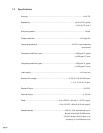
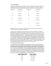
Order Code Shunt Range Order Code Shunt Range
01 0-10 sccm 07 0-1 slpm
02 0-20 sccm 08 0-2 slpm
03 0-50 sccm 09 0-5 slpm
04 0-100 sccm 10 0-10 slpm
05 0-200 sccm 11 0-20 slpm
06 0-500 sccm 12 0-40 slpm
13 0-70 slpm
Gases other than air or nitrogen have different properties, and the range of each shunt will be
different than those listed in the order codes above.
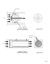
The flow rate of interest determines the size of the shunt required. As previously indicated, 13
separate shunts are required for the range of flow spanning 10 sccm to 70 slpm full scale. For the
200 sccm flow range, four Monel 400 tubes of 0.027" i.d. are located within the aluminum shunt
plug to accommodate the full 200 sccm. Lower flow rates require proportionally fewer tubes and
the unused holes are sealed with epoxy (or selected eutectic solder if epoxy is undesired). A single
304L stainless steel plug with an annular spacing of 0.009" with the base accommodates the 500
sccm flow range. Increasing the flow requires more annular passageways which is accomplished by
adding concentric cylinder shells with increasing gap dimensions. Eventually, a maximum annular
gap dimension for laminar flow is obtained (~0.030"). For a maximum flow rate of 60 slpm, three
annular regions using two brass concentric cylinders is required. To change ranges, a new shunt
must be installed and a calibration conducted to do further measurements.
2.6.5 Spanning the Digital Display
An exchange of shunt requires resetting of the digital display. Ideally, the flow should be estab-
lished to the full scale level consistent with the selected shunt and the display pot adjusted for that
full scale flow rate. It is also possible to disconnect the phone jack connector to the main body and
input 5.00VDC and set the display consistent with the particular full scale flow for the selected
shunt. Verify the full scale voltage/current output and adjust the display pot for that full scale flow
rate. It is also possible to disconnect the phone jack between the display and flowmeter, and supply
external power (+5 VDC) and a full scale voltage (0-5 VDC) to the display. Refer to the schemat-
ics of PCB-846 in section 6 of this manual. The display may then be adjusted consistent with the
particular full scale flow for the selected shunt. Note that there may be need to change the display
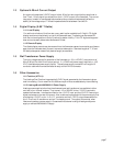
board solder jumpers in order to exhibit the new full scale flow rate.
Largest DisplaLargest Displa
Largest DisplaLargest Displa
Largest Displa
y y
y y
y
VV
VV
V
aluealue
aluealue
alue
Jumper SettingJumper Setting
Jumper SettingJumper Setting
Jumper Setting
1999. All jumpers open
199.9 JP 1 closed
19.99 JP 2 closed
1.999 JP 3 closed