


INSTALLATION OF STAND-BY POWER SYSTEMS
_I_DANGER
installation of Stand-By Electrical Power Systems should be done by a QUALIFIED electrtctam ALL APPLICABLE ELEC-
TRICAL AND BUILDING CODES MUST BE COMPLIED WITH. improper installation methods or procedures are EX-
TREMELY DANGEROUS add may damage equipment and personal property°
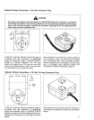
Alternator
F! om
Utility
Line
Meter _
Box _
1\
To Building
Circuits To.Bulid ing
Auxiliary Dist Circuits Powered
enter Circuits By Alternator
Building
Distribution I AuxiliaryBuilding
Panel _ DistributionCenter
(For-Alternator Powered
.... Circuit)
Cord Set
TYPICAL INSTALLATION
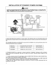
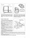
A typical Stand-By Power System is shown above° This System uses a (1) Connection Box and
Cord Set, (2) a Transfer Switch, (3) two Building Distribution Centers, and (4) interconnecting wir-
ing.
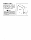
The CONNECTION BOX and CORD SET is used with the 120/240 volt, 4-prong, 20 amp outlet. The
following Stand-By Kits are available:
Model No. Connection Box and Cord Set Transfer Switch
580.322280 120/240 Volt, 4-wire cord set 100 Amp Manual
580.322290 !201240 Volt, 4-wire cord set 200 Amp Manual
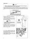
A TRANSFER SWITCH is required, to prevent electrical "feedback" between utility company
power lines and the alternator. Be sure to install the correct Transfer Switch, based on the
following:
1. if utility company input to the building is rated at LESS THAN 100 Amps, install a Switch hav-
ing a utility line connection rated at 100 Amps.
2. If utility company input to the building is rated at MORE THAN 100 Amps but LESS THAN 200
Amps, install a Switch having a utility line connection rated at 200 Amps.
3. Make sure the Transfer Switch alternator connection is rated at a higher amperage than the
alternator to be used.
4