


14 Raymarine Sunlight Viewable Marine Displays - Users Guide
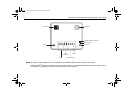
Extending the power cable
Longer power cable runs may require larger wire gauges to mini-
mize any voltage drop in the cable. Ensure that the minimum
voltage specification of the display is met at the junction of these
cables when the display is operating at full brightness.
If a longer power cable run is required, use the supplied power
cable to connect the free end to the extension cable; take partic-
ular care to ensure correct polarity and grounding of the
screening braid to the boat’s RF system.
The supplied power cable has a cross section of 12 AWG (3.3
mm
2
).
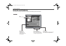
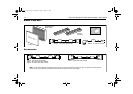
Cable runs
You need to attach one or more of the cables shown in “Typical
installation” on page 9. Consider the following points before
running any cables:
• All cables should be adequately secured, protected from
physical damage and exposure to heat. Avoid running cables
through bilges or doorways, or close to moving or hot
objects.
• Acute bends must be avoided.
• Where a cable passes through an exposed bulkhead or
deckhead, a watertight feed-through should be used.
• Secure cables in place using tie-wraps or lacing twine. Coil
any extra cable and tie it out of the way.
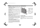
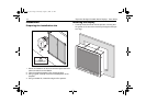
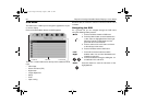
Display location and mounting options
Your display can be mounted using the flush mounting kit
supplied. Raymarine recommends that you power the unit and
select a suitable mounting location prior to installing the display.
When planning the display location, the following points should
be considered to ensure safe, comfortable and reliable
operation:
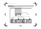
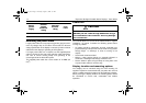
Boat’s
power
supply
Isolator
switch
minimum
rating
Thermal
breaker
rating
Fuse
value
12 V 15 A 8 A 12 A
24 V 8 A 4 A 6 A
CAUTION
Cable runs
DO NOT pull the cable through bulkheads using a
cord attached to the connector. this may damage
the connections
81277_1.book Page 14 Thursday, August 17, 2006 1:51 PM