


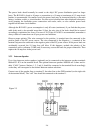

The power leads should normally be routed to the ship’s DC power distribution panel on larger
boats. The RAY430 is fused at 10 amps so connection to a 10 amp or (maximum of) 15 amp circuit
breaker is recommended. On smaller vessels the power leads may be connected directly to the main
battery, isolation switch, or circuit breaker. For best noise isolation from other shipboard electronics
avoid grouping the loudhailer power connections with radar, radio, or echo sounder power leads
together on the same circuit breaker.
Although the RAY430’s power consumption is only 65 watts (maximum), if you find that the power
cable leads need to be extended more than 10 feet, the wire size of the leads should be in-creased
accordingly to minimize line losses. For runs of 20-35 feet #12 AWG is recommended, remember to
always solder all connections on all your power cord additions.
Observe proper polarity! The wire connected to the positive (+) terminal must be connected to the
positive point of the DC power source; The wire connected to the Negative (—) terminal of the
terminal strip must be connected to the negative point of the DC power source. If the power leads are
accidentally reversed, the 10 Amp fuse will blow. If this happens, recheck the polarity of the
connections with a voltmeter (VOM) and, if necessary, reverse the leads for proper connection. Then
replace the 10 amp fuse in the power cord.
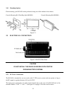
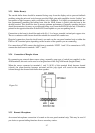
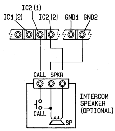
2.5.2 Intercom Speaker
Up to four intercom station speakers (optional) can be connected to the intercom speaker terminals
labeled IC1-IC4 on the terminal block. The optional intercom speakers M95998 are 8 ohms and in-
dude “CALL” buttons. Stations 1, 2, 3 and 4, should be connected to the terminal block accordingly
so that they will correspond to the desired Intercom station selections.
Connect one of the speaker lines to terminal 2, the other line to the GND terminal (on the right side
of the terminal block). The “call” line should be connected to the terminal 1.
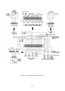
Figure 2-5
2-6