


SECTION 4
TECHNICAL DESCRIPTION
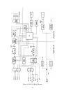
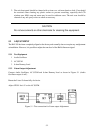
4.1 BLOCK DIAGRAM
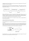
Figure 4-1 is the block diagram of the RAY43O. The operation of the circuitry described below is
based upon this block diagram.
1. 1. CPU
The CPU (U-203) accepts key entry from the keyboard and selects the proper input and out-
put signals to control devices.
2. Relay
Changes input/output signals and is controlled by the CPU.
3. Relay Driver
Selects the input and output speakers
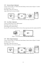
4. 5W Pre-Amp.
IC2 and IC3 amplifies low level voice signals and supplies them to the output signal selector
through Listen Volume VR 1.
5. Intercom Selector
Activates the Intercom speaker with selected keyboard or Call key.
6. Output Signal Selector
Select the output signal (Foghorn Signal, Intercom, Alarm or Mic input signal) to the Power
Amplifier
7. Power Amplifier
IC1 is a 30W power amplifier to active the selected speaker.
8. Interface Circuit
Senses the “CALL” or alarm sensor signals from the external unit. The photo couplers are
used to reduce any external noise pickup by isolation.
4-1