


ENGINE
3.18
7. Subtract valve stem measurement to obtain stem
to guide clearance. NOTE: Be sure to measure
each guide and valve combination individually.
8. Replace v alve and/or guide if clearance is
excessive. Compare to specifications.
Valve Guide I.D.:
.2362-.2367I (6.0-6.012 mm)
NOTE: If valve guides are replaced, valve seats must
be reconditioned. Refer to Valve Seat Reconditioning
for procedure.
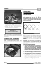
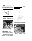
COMBUSTION CHAMBER
Clean all accumulated carbon deposits from
combustion chamber and valve seat area with a soft
wire brush.
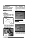
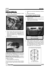
VALVE SEAT
RECONDITIONING
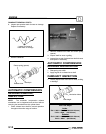
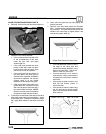
Valve Seat Inspection
Inspect valve seat in cylinder head for pitting, burnt
spots, roughness, and uneven surface. If any of the
above conditions exist, the valve seat must be
reconditioned. See Valve Seat Reconditioning, Page
3.19--3.21. If the valve seat is cracked the cylinder
head must be replaced.
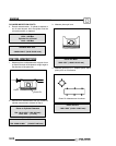
Too
Wide
Uneven
Good
Too
Narrow
Cylinder Head Reconditioning
NOTE: Servicing the valve guides and valve seats
requires special tools and a thorough knowledge of
reconditioning techniques. Follow the instructions
provided in the Valve Seat Reconditioning Kit (PN
2200634).
CAUTION: Wear eye protection when performing
cylinder head service. Valve guide replacement will
require heating of the cylinder head. Wear gloves to
prevent burns.
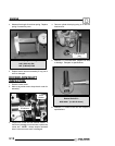
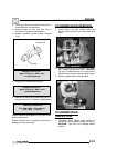
Valve Guide Removal/Installation
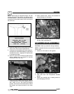
1. Remove all carbon deposits from the combustion
chamber, valve seat and valve guide area before
attempting to remove valve guides. CAUTION:
Carbon deposits are extremely abrasive and may
damage the valve guide bore when guides are
removed.
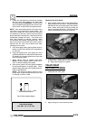
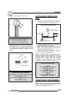
2. Place new valve guides in a freezer for at least 15
minutes while heating cylinder head.
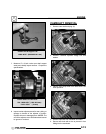
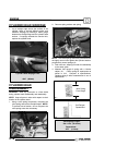
3. Heat cylinder head in an oven or use a hot plate to
bring cylinder head temperature to 212° F (100°
C). CAUTION: Do not use a torch to heat
cylinder head or warpage may result from uneven
heating. Head temperature can be checked with
a pyrometer or a welding temperature stick.