ENGINE
3.5
PISTON IDENTIFICA
TION
The piston may have an identification mark or the
piston may not
have an identification mark for
piston placement. If the piston has an identification
mark, follow the directions for piston placement
below. If the piston does not have an identification
mark, the direction for placement of the piston does
not matter.
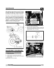
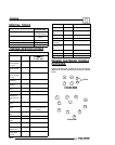
Note the directional and identification marks when
viewing the pistons from the top. The letter “F”, “ !
”, “ "”or: must always be toward the flywheel side
of the engine. T he other numbers are used for
identification as to diameter, length and design. Four
stroke engine rings are rectangular profile. The
numbers or letters on all rings (except oil control rings)
must be positioned upward. See text for oil control
ring upper rail installation. Use the information below
to identify pistons and rings.
Engine
Model No.
Oversize
Available*
(mm)
Standard
Piston
Identification
ES32PFE .25
.50
None
*Pistons and rings marked 25 are .25mm (.010I)
oversized. Pistons and rings marked 50 are .50mm
(.020I)oversized
ACCESSIBLE COMPONENTS
The following components can be serviced or
removed with the engine installed in the frame:
G Flywheel
G Alternator/Stator
G Starter Motor/Starter Drive
G Cylinder Head
G Cylinder
G Piston/RIngs
G Oil pump
G Rocker Arms
G Cam Chain and Sprockets
The following components require engine
removal for service:
G Camshaft
G Connecting Rod
G Crankshaft
G Crankshaft Main Bearings
G Crankcase
ENGINE REMOVAL
1. Clean work area.
2. Thoroughly clean the ATV engine and chassis.
3. Disconnect battery negative (-) cable.
4. Remove the following parts as required.
G Seat
G Left and Right Side Covers (Refer to
Chapter 5)
G Fuel Tank Cover / Front Cab (Refer to
Chapter 5)
G Fuel Tank (Refer to Chapter 4)
5. Disconnect spark plug high tension lead.
6. Disconnect all electrical wires from the engine.
7. Remove springs from exhaust pipe and remove
pipe.
8. Drain engine oil.
9. Remove airbox.
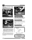
10. Remove carburetor. Insert a shop towel into the
carburetor flange to prevent dirt from entering the
intake port.
11. Loosen auxiliary brake master cylinder mount if
necessary for clearance.
12. Refer to PVT System Chapter 6 to remove outer
clutch cover, drive belt, drive clutch, driven clutch,
and inner cover.
13. Starter motor. Note ground cable location. Mark
positive (+) cable mounting angle and remove
cable.
14. Remove transmission linkage rod(s) from gear
selector and secure out of the way.
15. Remove engine to chassis ground cable.
16. Remove all engine mount nuts and / or engine
mount plates.
17. Remove engine through right side of frame.


