


Bluetooth QuickStart Kit Version 1.0 - User’s Guide Page 26
Copyright 2004-2005 © Embedded Artists AB
J6 – CTS
The application program has the
option of controlling the RTS/CTS
signals on the RS232 serial
channel, if needed.
If used, signal P0.22 is the CTS
signal and P0.22 must be an
output.
Jumper shorted = Pin P0.22 act as RS232-CTS signal.
P0.22 must be an output.
Jumper open = Pin P0.22 is free to be used for
other tasks (default position)
J8 – Serial Channel Select
The serial channel of the Bluetooth
module can be connected either to
the LPC2106 microcontroller or
the RS232 serial channel.
Jumper shorted = LPC2106 communicate with
Bluetooth module (default
position)
Jumper open = Bluetooth module is connected
directly to the RS232 serial
channel. Use this position when
connectBlue’s Serial Port Adapter
Wizard is used.
J10 – Manual Bootloader
If signal P0.14 is sampled low after
reset, the internal bootloader in the
LPC2106 microcontroller is
activated.
Jumper shorted = Signal P0.14 grounded
Jumper open = Signal P0.14 left untouched, i.e.,
not pulled low (default position)
SW2 – Automatic Bootloader
By using the automatic bootloader
feature, the RTS/DTR signals in
the RS232 serial channel can
control the reset and bootloader
activation signal.
Position up = Active automatic bootloader
(switch is “to” the DSUB-9
connector)
Position down = Disable the automatic bootloader
(switch is “from” the DSUB-9
connector)
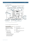
Table 3 – Board Jumpers and Switch