


Bluetooth QuickStart Kit Version 1.0 - User’s Guide Page 25
Copyright 2004-2005 © Embedded Artists AB
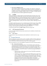
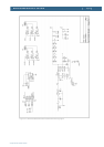
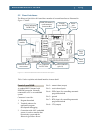
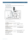
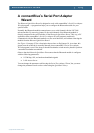
5.4 Board Jumpers
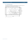
There are six jumpers and one switch on the board. These are illustrated in Figure 18 and
explained in Table 3 below.
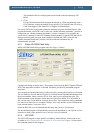
Figure 18 – Jumper Description
The table below explains the different jumpers.
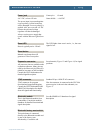
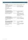
J3 – DBGSEL
Enable or disable the LPC2106
JTAG interface
Jumper shorted = Enable JTAG
Jumper open = JTAG not enabled (default
position)
J4 – RTCK
Some JTAG interfaces require the
JTAG signal RTCK to be
grounded. Please consult your
JTAG interface manual for details.
Jumper shorted = JTAG signal RTCK grounded
Jumper open = JTAG signal RTCK is left
untouched (default position)
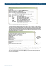
J5 – RTS
The application program has the
option of controlling the RTS/CTS
signals on the RS232 serial
channel, if needed.
If used, signal P0.23 is the RTS
signal and P0.23 must be an input.
Jumper shorted = Pin P0.23 act as RS232-RTS signal.
P0.23 must be an input.
Jumper open = Pin P0.23 is free to be used for
other tasks (default position)
Automatic bootloader enabled
Automatic bootloader not enabled
J3
J4
J5
J6
J8
J10