


Bluetooth QuickStart Kit Version 1.0 - User’s Guide Page 22
Copyright 2004-2005 © Embedded Artists AB
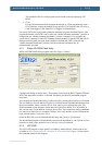
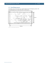
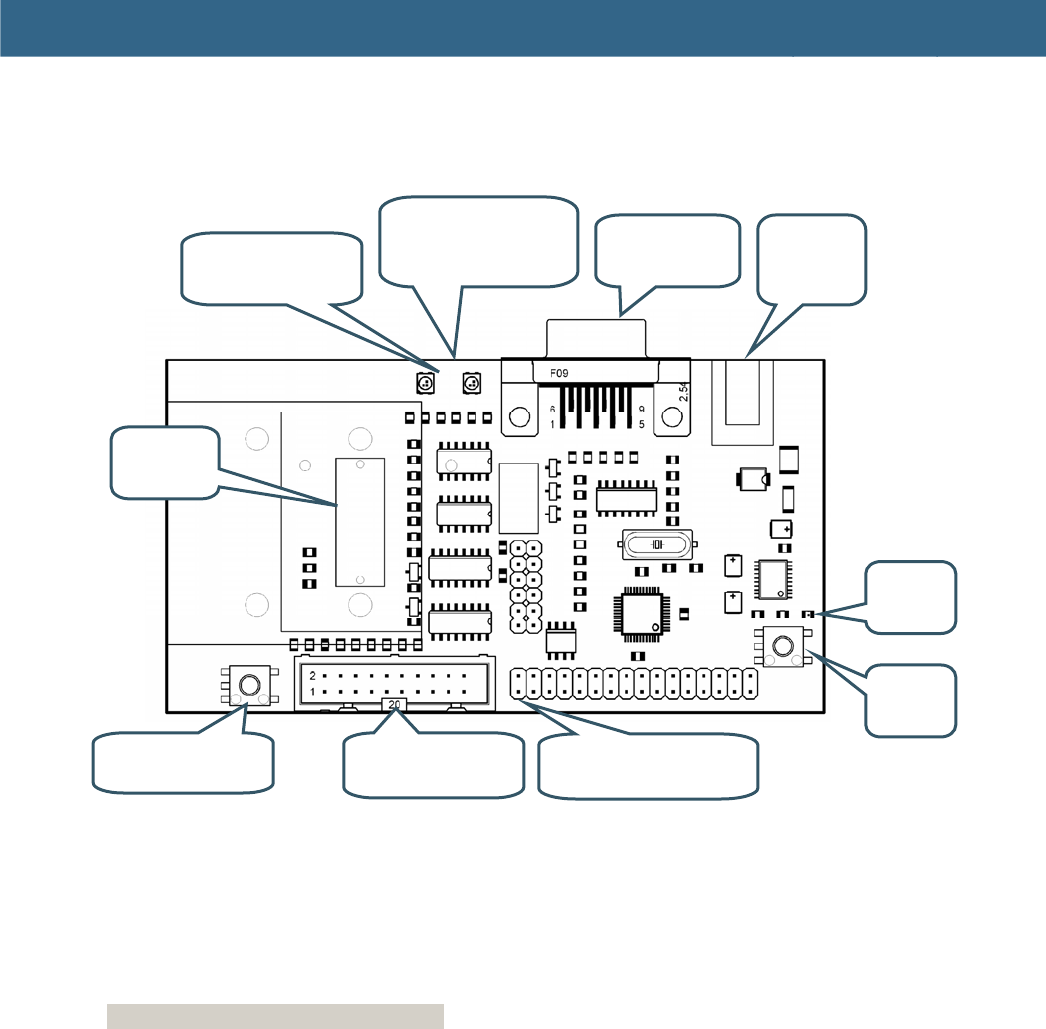
5.2 Board Interfaces
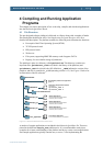
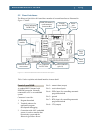
The Bluetooth QuickStart Kit board has a number of external interfaces as illustrated in
Figure 17 below.
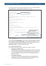
Figure 17 – Bluetooth QuickStart Board Interface Description
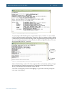
Table 1 below explains each board interface in more detail.
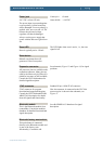
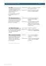
Female 9-pos DSUB
A standard RS232 channel with
ESD/EMI protection. Normally
connected to a PC or an embedded
system.
Connector is used for:
1. Program download
2. Terminal printouts for
application program
development debugging
3. Connection with ANY embedded
system, in order to transfer data
between the system and the
Bluetooth QuickStart Board.
Pin 2 = transmit data (output)
Pin 3 = receive data (input)
Pin 4 = DTR (input) for controlling automatic
program download
Pin 5 = ground
Pin 7 = RTS (input) for controlling automatic
program download
Pin 8 = CTS (output)
Bluetooth factory
reset switch
JTAG connector
for LPC2106
Expansion connector
(p
in #1
)
Reset
button
Reset
LED
Bluetooth
module
Status indicating
RGB LEDs
Female
9-pos DSUB
Power
jack
2.1 m
m
MMC/SD memory
card connector
(
bottom side
)