


Bluetooth QuickStart Kit Version 1.0 - User’s Guide Page 23
Copyright 2004-2005 © Embedded Artists AB
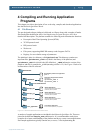
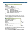
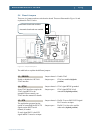
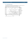
Power jack
4-6 V DC, at least 150 mA.
The power input is protected against
reverse polarity, but the board may
still be damaged if reverse polarity is
applied. Also, never exceed +6V DC
because the on-board voltage
regulator will then be damaged.
Always use the power supply that
comes with the Bluetooth QuickStart
Kit.
Center pin = Ground
Outer shield = +4-6V DC
Reset LED
Reset is typically active 120 mS.
The LED lights when reset is active, i.e., the reset
signal is low.
Reset button
Manual reset button that will
generate a 120 mS reset pulse.
Expansion connector
All processor pins are available at the
expansion connector. Many pins are
used by the Bluetooth QuickStart Kit
platform, but some are still available.
Consult the LPC2106 datasheet for
detailed signal description.
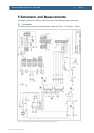
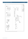
See schematic (Figure 15 and Figure 16) for signal
positions.
JTAG connector
JTAG connector for program
download and program debugging.
Consult the LPC2106 datasheet and
ARM JTAG description for details
about all signals and functionality.
Standard 20 pos. ARM JTAG connector.
How the connector is connected to the LPC2106
processor pins is shown in the schematic, see
Figure 15.
Bluetooth module
This is the Bluetooth module from
connectBlue. Consult the modules
datasheet for detailed functional and
signal description.
See cB-OEMSPA-13i datasheet for signal
description
Bluetooth factory reset switch
This push-button is connected
directly to the Bluetooth module and
is part of the factory reset
functionality. Consult the cB-