


9
LA000578A © 2006 Navman New Zealand. All rights reserved. Proprietary information and specifications subject to change without notice.
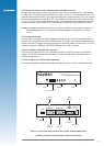
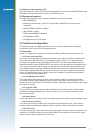
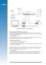
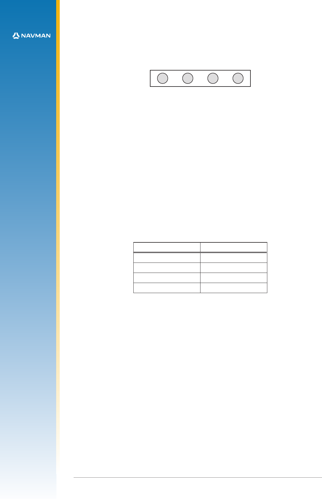
3.3 Function LEDs
There are four LEDs on the front panel of the development unit, indicating the status of a
selection of basic functions. The functions of the LEDs are described in the sections that follow.
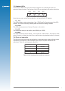
1PPS Power AUX GPIO
Figure 3-3 Function LEDs on front panel
Note that some early versions of the evaluation unit have different LED legends.
3.3.1 1PPS
This LED will ash on with each transition of the 1 PPS (Pulse Per Second) output of the GPS
receiver. The 1PPS LED will begin ashing when the receiver is tracking a satellite.
3.3.2 Power
This LED indicates presence of primary DC power to the module.
3.3.3 AUX
This LED shows activity on the auxiliary serial RS232 port (DGPS).
3.3.4 GPIO
This LED indicates the state of GPIO15 , which can be set via DIP switch 2. This LED is lit when
switch 2 is set to on. (Note that switch 2 has no effect when using standard Jupiter 30 software.)
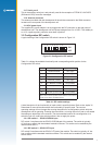
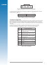
3.4 Clock out connector
The Clock out connector provides an interface for all associated timing signals with the module.
It provides the user access to the Time Mark (1PPS) signal. The pinout connections are
described in Table 3-2, and illustrated in Figure 3-4.
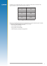
Pin number Function
1 not used
2 inverted 1PPS signal
3 normal 1PPS signal
4 ground
Table 3-2 Pin functions of the clock out connector