


6
LA000578A © 2006 Navman New Zealand. All rights reserved. Proprietary information and specifications subject to change without notice.
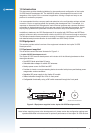
6. Software and documentation CD
The CD contains the Jupiter 30 GPS receiver data sheet, PC Analysis software (SiRFDemo and
SiRFash), and other information on how to use GPS receivers.
2.2 Equipment required
The following equipment is also required to evaluate the Jupiter 30 receiver.
• IBM compatible PC
• Minimum one serial port (If your PC only has USB, a USB/RS232 converter can be
employed)
• Windows 95/98, WinNT4.0 or higher
• 486 100MHz or higher
• SVGA at least 800x600 resolution
• 16 Megabytes of RAM
• 6 Megabytes (min) of disk space
3.0 Technical conguration
This section provides a detailed description of all the technical aspects and congurable
functionality of the Jupiter 30 GPS development unit.
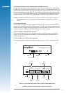
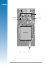
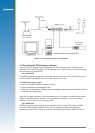
3.1 Overview
Figure 3-1 illustrates the connectors, switches and LEDs available on the development unit.
3.1.1 Power switch (On/Off)
The switch on the front panel controls primary power to the Jupiter 30 receiver module inside.
The power status LED (see section 3.3) indicates the state of the unit: if lit, the module has
primary power supplied. If the conguration DIP switch 5 is on and Jumper JB5/6 linked, the
module’s secondary supply SRAM and RTC will continue to be powered when the power switch
is off. Only the removal of the DC power input at the rear of the unit will stop secondary power
being applied (assuming Jumper JB5/6 and switch 5 are correctly set). Having this secondary
power supply applied means that the Jupiter 30 will have a ‘hot start’ capability when primary
power is re-applied within 4 hours, and a ‘warm start’ thereafter, by maintaining last position,
current time and satellite ephemerides.
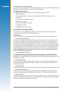
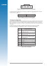
3.1.2 Conguration DIP switch
The conguration DIP switch on the front panel provides the ability to congure the Jupiter
30 module, offering exibility depending on the specic application. Refer to section 3.2 for a
description of the functionality of each individual switch, including the typical settings when using
the Jupiter 30 module.
3.1.3 Function LEDs
The four LEDs on the front panel provide an indication of the current status of basic features
associated with the development unit. Refer to section 3.3 for a complete description of the
function of each LED.
3.1.4 Reset switch
A reset push button is provided on the front panel to generate a receiver system hardware reset.
3.1.5 Clock out connector
The Clock out connector, located on the rear panel of the development unit, can be used to
provide module generated timing signals. Refer to section 3.4 for more detailed information.
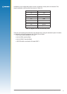
3.1.6 Serial port 1
This host serial port is used to send and receive serial data. This port is used as the default, with
transmission in NMEA format at the rate of 9600 Baud. The connectors to be used with these
serial ports are 9-pin D-subminiature connectors.