


13
LA000578A © 2006 Navman New Zealand. All rights reserved. Proprietary information and specifications subject to change without notice.
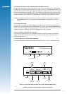
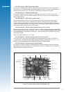
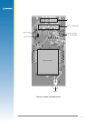
3.6 Jupiter 30 module on adapter board
Figure 3-6 (on the following page) shows the adapter board with the positions of the connectors
and indicators.
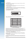
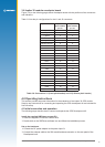
Table 3-6 lists the pin congurations for the J1 and J2 connectors.
Jupiter function J2 (2.54 mm
pitch header)
pin no.
J1 (2 mm
pitch header)
pin no.
V_ANT 1 1
VCC_RF 2
V_BATT 3 3
VDD 4 4
M_RST 5 5
GPIO3/GYRO IN 6 6
GPIO15/FR 7 7
BOOT 8 8
GPIO1/W TICKS 9 9
RFON 10
GND 10
TXA 11 11
RXA 12 12
GPIO4 13
GND 13
TXB 14 14
RXB 15 15
Wake-up 16
GND 17 16
GPIO13 18
GND 17
GND 18
1PPS 19 19
GPS_FIX/GPIO10 20
Table 3-6 Connections J1 (2 mm pitch header) and J2 (2.54 mm pitch header)
4.0 Operating instructions
This section provides important information for the evaluation of the Jupiter 30 GPS module.
Step-by-step instructions for connecting and operating the GPS development kit are included for
rst time setup.
4.1 Initial connection and operation
The following steps describe how to connect and operate the GPS Development Kit.
Install the supplied SiRFdemo on your PC:
1. Insert the supplied CD into the CDROM drive
2. Double click on the SiRFDemo software icon and follow the installation process.
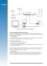
Set up the hardware:
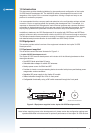
1. Connect the DC power adapter to the power input J1.
2. Connect the antenna cable to the SMA coaxial antenna connector on the rear panel of the
Development unit.