


Contents
Related products ................................................................................................................ 1
Related documents ............................................................................................................ 1
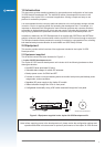
1.0 Introduction .......................................................................................................4
2.0 Equipment..........................................................................................................4
2.1 Equipment supplied ...................................................................................................... 4
2.2 Equipment required ...................................................................................................... 6
3.0 Technical conguration ....................................................................................6
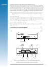
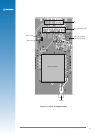
3.1 Overview ....................................................................................................................... 6
3.1.1 Power switch (On/Off) ........................................................................................... 6
3.1.2 Conguration DIP switch ...................................................................................... 6
3.1.3 Function LEDs ...................................................................................................... 6
3.1.4 Reset switch ......................................................................................................... 6
3.1.5 Clock out connector .............................................................................................. 6
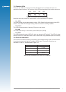
3.1.6 Serial port 1 .......................................................................................................... 6
3.1.7 Serial port 2 .......................................................................................................... 7
3.1.9 Antenna connector ............................................................................................... 7
3.1.10 DC power input ................................................................................................... 7
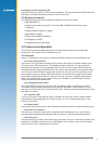
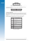
3.2 Conguration DIP switch .............................................................................................. 7
3.2.1 DIP switch 1 – GPIO3 /GYROIN input ................................................................. 7
3.2.2 DIP switch 2 – GPIO15 /FR input ......................................................................... 7
3.2.3 DIP switch 3 – BOOT from serial mode ............................................................... 8
3.2.4 DIP switch 4 – GPIO1/W_TICKS input ................................................................. 8
3.2.5 DIP switch 5 – RTC backup power enable ........................................................... 8
3.2.6 DIP switch 6 – Antenna preamp power select (3.3 V or 5/12 V) .......................... 8
3.2.7 DIP switch 7 – Antenna preamp power select (5 V or 12 V) ................................ 8
3.2.8 DIP switch 8 – Antenna preamp power enable .................................................... 8
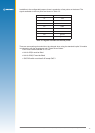
3.3 Function LEDs .............................................................................................................. 9
3.3.1 1PPS ..................................................................................................................... 9
3.3.2 Power ................................................................................................................... 9
3.3.3 AUX ...................................................................................................................... 9
3.3.4 GPIO .................................................................................................................... 9
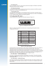
3.4 Clock out connector ..................................................................................................... 9
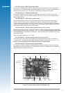
3.5 Internal conguration ...................................................................................................11
3.6 Jupiter 30 module on adapter board ...........................................................................13
4.0 Operating instructions ................................................................................... 13
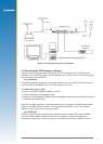
4.1 Initial connection and operation ..................................................................................13
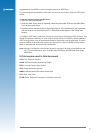
4.2 Positioning the GPS antenna ......................................................................................14
4.3 Connecting an RTCM differential source ....................................................................14
4.4 Operating the GPS Analyser software ........................................................................15
4.4.1 VisualGPS ...........................................................................................................15
4.4.2 SiRFDemo ...........................................................................................................15
5.0 Acronyms used in this document ................................................................. 16