


8
LA000578A © 2006 Navman New Zealand. All rights reserved. Proprietary information and specifications subject to change without notice.
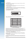
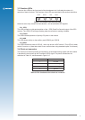
3.2.3 DIP switch 3 – BOOT from serial mode
DIP switch 3 interfaces with the BOOT pad of the module and allows the user to upgrade the
Flash memory. For normal operation the switch should be set to off. To boot from the serial port
the switch should be set to on. This switch is enabled by the internal switch SW3.3.
3.2.4 DIP switch 4 – GPIO1/W_TICKS input
DIP switch 4 interfaces to the GPIO1/W_TICKS pad of the module. The switch is typically
off, but has no effect with the standard module’s software. This switch can be enabled by the
internal switch SW3.4.
3.2.5 DIP switch 5 – RTC backup power enable
DIP switch 5 provides control of the RTC backup power to the module. When set to the on
position, the RTC backup power is applied to the module, allowing the RTC and SRAM to
continue being powered when the primary source is removed. The jumper JB5/6 must also be
in place for the backup power to be supplied. This power supply will be supplied to the module
even with the main power switch in the off position.
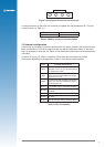
3.2.6 DIP switch 6 – Antenna preamp power select (3.3 V or 5/12 V)
Dip switch 6 provides control of the antenna preamp voltage applied to the module. The switch
position determines the supply voltage (off = 3.3 V, on = 5/12 V). Switch 6 should be left in the
3.3 V (off) position. The positions of switches 7 and 8 also need to be considered when using
the preamp function.
Note: the supplied antenna is a 3.3 V type.
3.2.7 DIP switch 7 – Antenna preamp power select (5 V or 12 V)
DIP switch 7 also controls the antenna preamp voltage applied to the module. If switch 6 is
on, then switch 7 will determine the supply voltage to the active antenna (off = 12 V, on = 5 V).
Switch 7 is not operational when switch 6 is in the 3.3 V (off) position.
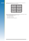
3.2.8 DIP switch 8 – Antenna preamp power enable
DIP switch 8 provides the ability to enable/disable the antenna preamp voltage to the module
depending on the antenna being used. Typically this switch is on, enabling 3 V to be applied to
the active antenna supplied with the kit.
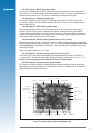
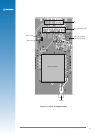
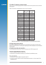
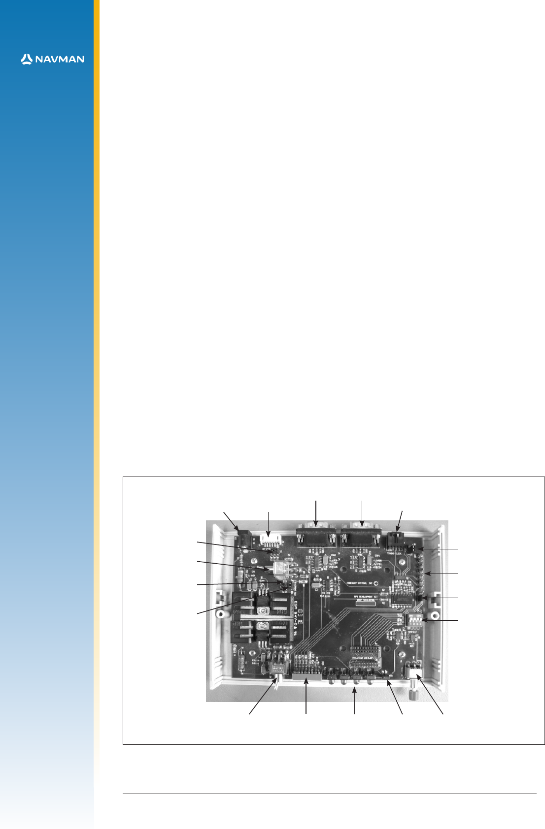
Figure 3-5 Internal layout of the development unit
ON/OFF switch conguration DIP
switch
function LEDS JB5/6 reset switch
serial port 1
serial port 2
timing connector
DR connector
DC power
JB10/11/12
voltage selection
switch (3.3V or 5V)
JB1/2
JB3/4
JB13/14/15
test points E1 to E9
JB16/17
SW3
all off except SW3.3