


4
LA000578A © 2006 Navman New Zealand. All rights reserved. Proprietary information and specifications subject to change without notice.
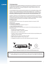
1.0 Introduction
This document provides detailed guidelines for the operation and conguration of the Jupiter
30 GPS Module Development Kit. The AA003029 series of development kits assist in the
integration of the Jupiter 30 in a customer’s application, offering a simple and easy to use
platform for evaluation purposes.
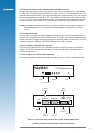
It is recommended that the user pays particular attention to the conguration settings outlined
in section 3.0 prior to applying power and operating the development unit. For example, it is
important to understand and recognise the main functional switches and connector locations
accessible on the development unit’s front and rear panels. Following this information, simple
step-by-step guidelines are presented to ensure successful setup of the development unit.
In addition to hardware, the GPS Development Kit is supplied with SiRFDemo and SiRFash
analysis software to allow communication with the Jupiter 30 GPS receiver through a serial port.
The Windows based software presents the receiver’s raw data in a geographical form, allowing
both detailed analysis and evaluation for both NMEA and SiRF Binary formats.
2.0 Equipment
This section provides a brief overview of the equipment included in the Jupiter 30 GPS
Development Kit.
2.1 Equipment supplied
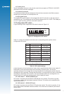
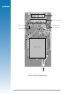
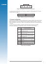
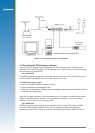
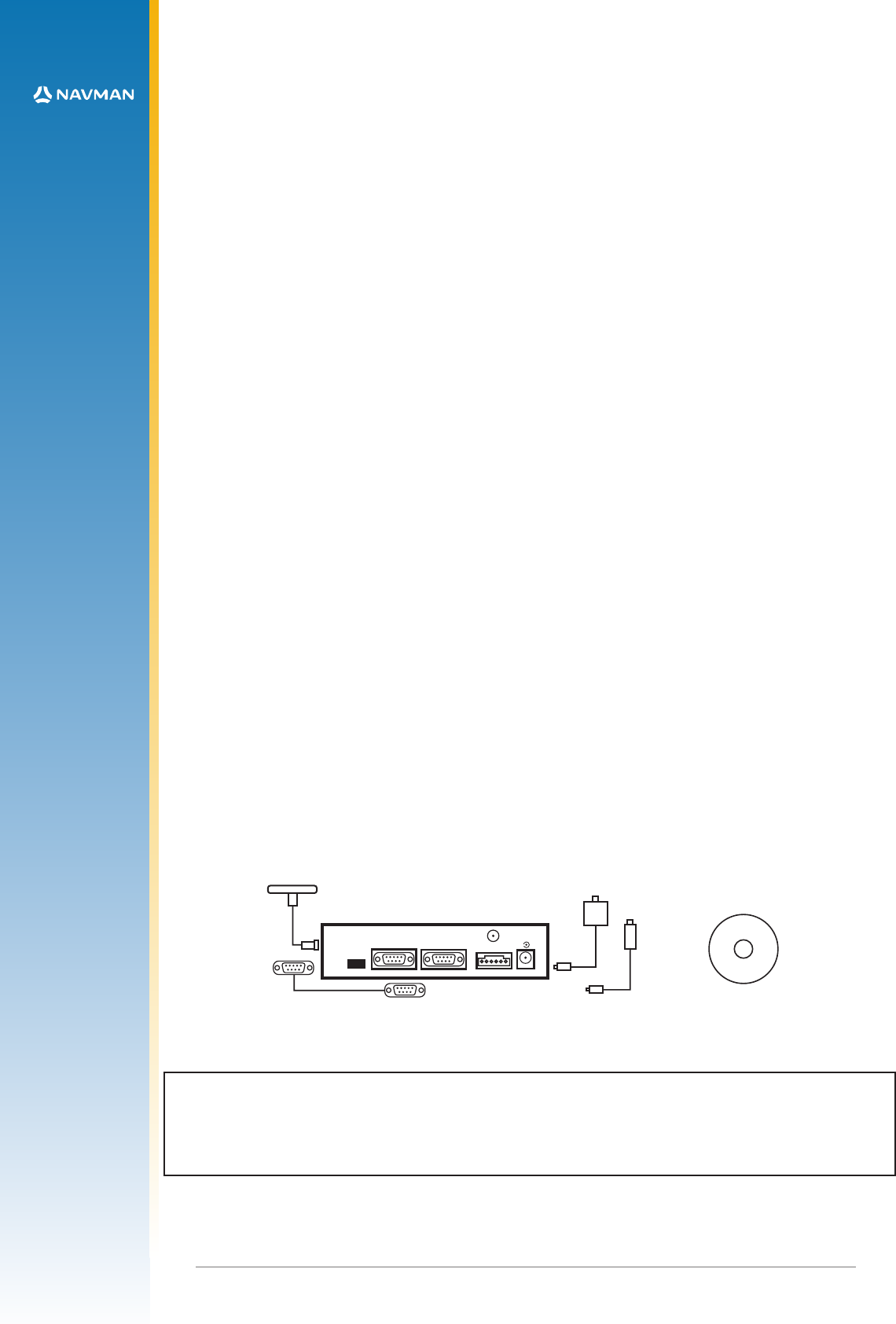
This kit should contain the items illustrated in Figure 2-1.
1. Jupiter 30 GPS development unit
The Jupiter 30 GPS receiver development unit includes all of the following hardware to allow
thorough evaluation:
• Dual RS232 level serial data I/O ports
• Selectable bias voltages for active GPS antennas
• Backup power source for SRAM and RTC
• Provision to insert a current measuring device to monitor both primary and backup power
usage under various conditions
• Regulated DC power supply to the Jupiter 30 module
• Status indication through four LEDs on front panel
• Congurable functionality using a DIP switch accessed through the front panel
Figure 2-1 Equipment supplied in the Jupiter 30 GPS Development Kit
Note: before supplying power to the development unit, please review the conguration settings and
operation described in this document for optimum performance of the Jupiter 30 GPS receiver.
(1)
(2)
(3)
(4)
(5)
(6)
software and documentation
Serial Port 1
Antenna
DR
Clock
Out
Serial Port 2
-
+
DC Power
9-16Volts