


14
LA000578A © 2006 Navman New Zealand. All rights reserved. Proprietary information and specifications subject to change without notice.
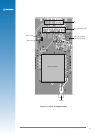
3. Connect the DB9 serial data cable between the PC serial communication port and the
development unit’s Serial Port 1.
4. Place the antenna in a site where a good view of the sky can be seen (refer to section 4.2 for
more detail).
5. Run the GPS analyser software on the PC. (Refer to section 4.4 for more details.)
6. Connect the power supply to a suitable AC outlet.
7. Turn the unit on using the power switch on the front panel to provide primary power to the
Jupiter 30 receiver. Once power is applied, the Power LED should be lit.
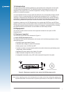
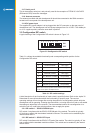
4.2 Positioning the GPS antenna
The GPS antenna should be located with a clear view of the sky for optimal reception of the
satellite signals. The 1PPS LED should begin ashing at 1 Hz once the receiver is powered
and has started receiving at least one satellite. This provides an indication of whether or not the
receiver is running.
Note: GPS signals may be severely attenuated or totally obscured by roofs, solid walls, dense
foliage, or even coated glass (found in many ofce structures and car windows). The
development unit should be outside, or on the roof of a building to effectively evaluate
receiver performance. With stationary developments, care should be taken to keep the
antenna away from the side of a building as GPS signals can reect off metal or coated
glass. These reections have a longer path than direct signals and can cause multi-path
errors.
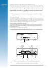
4.3 Connecting an RTCM differential source
For debugging purposes, it is suggested that users log both the GPS and RTCM data
simultaneously. To allow the provision to do this, Navman can supply a software program called
Labmon.
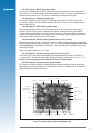
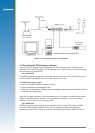
The development unit, PC and the RTCM SC-104 differential correction source are connected
as shown in Figure 4.1. If RTCM SC-104 data needs to be logged at the same time it is sent
to the receiver, the OEM must supply a cable with three connectors to connect the RTCM
correction source to the development unit’s auxiliary port and to an unused serial port on the
PC. In this case, data is only logged when Labmon is invoked with le names as command line
arguments (refer to the Labmon application note LA010103). Logging and subsequent review of
the RTCM correction data often resolves performance or compatibility issues.
The development unit should be set up as shown in Figure 4-1 with only the RTCM correction
source connected to the receiver. If the RTCM cable is not connected to the receiver’s auxiliary
port, DGPS operation will not be possible. When RTCM data is being received the AUX LED will
be lit.
Note: the development unit may be connected to either the COM1, COM2, COM3, or COM4
serial ports and the RTCM differential correction data source connected either directly to
the receiver’s auxiliary I/O port, to one of the remaining serial ports of the PC, or to both
using an OEM-supplied three-connector serial cable.